
Install Instructions

14004911-001 ADAPTOR PLATE ASSEMBLY
Install New Thermostat
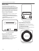
Feed the tubes through the large hole in adapter plate
(Fig. 4).
Match holes of the adapter plate to the wall screw
holes. Mount adapter plate using screws retained. Do
NOT over-tighten the screws.
HOLES CODED PER MANUFACTURER
PILOT HOLE FOR #6
(EXAMPLE: J = JOHNSON, P = POWRES,
R = ROBERTSHAW)
SELF-TAPPING
SCREW (PROVIDED)
PILOT HOLE FOR #6 SELF-TAPPING
TUBING
SCREW (PROVIDED)
C2837-1
Fig. 4. Adapter Plate Installation.
NOTE: If any wall screw holes coincide with the
noncoded pilot holes on the adapter plate
(Fig. 4), proceed as follows (If not, continue
with Step 3.):
With adaptor plate away from the wall, ream
out or strip the noncoded pilot holes by
tightening the screws retained when removing
the old mounting plate. Tighten with enough
force so that the screws move freely. Remove
and retain screws. If the wall screw holes are
larger than #6, enlarge the adapter plate holes
to allow enough clearance for the screws.
When adapting to a Johnson thermostat, if the
holes in the wall are out of alignment with the
adapter plate holes, use any available hole for
an additional wall anchor.
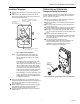
After removing temporary plug, push tubes onto the
thermostat backplate (mainline tube has air blowing out
and must be connected to the M barb connection on
rear of backplate).
Attach backplate (provided with thermostat) to adapter
plate with thread-forming screws provided with the
thermostat. Do NOT over-tighten the screws.
Continue to install thermostat referring to instructions
provided with it.
TP9610A 1006 and TP9613A 1000
Changeover Spring Replacement
Use the following procedure if the thermostat is a TP9610A
1006 or TP9613A 1000, and a 14001992-001 changeover
spring is required (see Table 1).
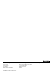
Using a screwdriver, carefully remove the screw and
changeover adjustment spring (Fig. 5).
Replace the spring, then carefully position and replace
the screw.
Ensure that main line pressure is set to low pressure
requirement (16 psi).
Turn the setpoint indicator adjustment until the setpoint
indicator reads 5F (2.8C) below actual temperature.
BLP gage should read 16 psi (90 kPa) (DA). If it does
not, turn changeover adjustment screw clockwise until it
does.
Turn the changeover adjustment screw
counterclockwise until the pressure begins to decrease
(DA). This indicates changeover. Allow the gage to go
to 0 psi (0 kPa) (DA).
Turn the changeover adjustment screw
counterclockwise until the pressure increases to full
main line pressure (DA). Turn the changeover
adjustment screw an additional 1/8 to 1/4 turn
clockwise. Changeover is calibrated.
M12137
14001992-001
16/21 PSI
CHANGEOVER
SPRING
SCREW
Fig. 5. Changeover Spring Replacement and Ajustment.
3
95-7549