
Install Instructions
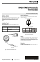


TP970-TP973 PNEUMATIC THERMOSTATS
Calibration Check
To check calibration, the control space temperature must
be within the scale range of the thermostat.
On direct-acting bimetal elements:
1. Turn setpoint down five degrees below actual room
temperature and allow thermostat to build up
branchline pressure.
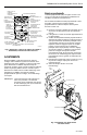
2. Turn setpoint indicator (Fig 4) up slowly.
3. If thermostat begins to bleed off between 1F (0.5C)
and 3F (1.5C) below room temperature, no further
calibration is necessary.
On reverse-acting, bimetal elements:
1. Turn setpoint up five degrees above actual room
temperature as measured by a test
thermometer, and allow thermostat to build up
branchline pressure.
2. Turn down setpoint indicator (Fig. 4) slowly.
3. If thermostat begins to bleed off between 1F (0.5C)
and 3F (1.5C) above room temperature, no further
calibration is necessary.
Calibration
CAUTION
The thermostat is very sensitive and should
not be heated by excessive handling during
calibration.
NOTE: Reference in the following procedures to a 30 psi
gage implies the gage and gage adapter listed in
INSTALLATION TOOLS section.
TP970
1. Remove the thermostat cover and install a 30 psi
gage into the gage tap.
2. Set the temperature setpoint indicator at the
indicated temperature.
3. Turn the calibration screw (see Fig. 4) until the gage
reads 0 psi.
4. Turn the calibration screw in the opposite direction
until the gage reads 8 psi (56 kPa) plus or minus 1
psi (7 kPa). The thermostat is now calibrated.
5. Remove the gage and replace cover.
TP971
1. Remove the thermostat cover and install a 30 psi
gage into the gage tap.
2. Set the temperature setpoint indicator at the
indicated temperature.
3. With 13 psi (91 kPa) (DAY) main air pressure, turn
the DAY (left) calibration screw (see Fig. 4) until the
gage reads 0 psi.
4. Turn the calibration screw in the opposite direction
until the gage reads 8 psi (56 kPa) plus or minus 1
psi (7 kPa).
5. With 18 psi (126 kPa) (NITE) main air pressure,
rotate the night setpoint dial until its setting agrees
with the indicated temperature.
6. Repeat Steps 2, 3, and 4 using the NITE setpoint
and (right) calibration screw. The thermostat is now
in calibration.
7. Remove the gage and replace cover.
TP972
1. Remove the thermostat cover and install a 30 psi
gage into the gage tap.
2. Set the temperature setpoint indicator to the
indicated temperature.
3. With 13 psi (91 kPa) (SUMMER) main air pressure,
turn the SUMMER (left) calibration screw (see Fig.
4) until the gage reads 0 psi.
4. Turn the calibration screw in the opposite direction
until the gage reads 8 psi (56 kPa) plus or minus 1
psi (7 kPa).
5. With 18 psi (126 kPa) (WINTER) main air pressure,
repeat Steps 3 and 4, using the WINTER (right)
calibration screw. The thermostat is now in calibra-
tion.
6. Remove the gage and replace the cover.
TP973
Same as TP970.
Home and Building Control
Home and Building Control
Honeywell Inc.
Honeywell Limited-Honeywell Limitée
Honeywell Plaza
155 Gordon Baker Road
P.O. Box 524
North York, Ontario
Minneapolis, MN 55408-0524
M2H 3N7
Printed in U.S.A. on recycled
paper containing at least 10%
post-consumer paper fibers.
www.honeywell.com
95-7478EF B.B. 9-99