
Install Instructions


TP970-TP973 Pneumatic
Thermostats
INSTALLATION
These instructions cover mounting the thermostat to a wall
without additional hardware. For replacement of existing
competitive and older Honeywell thermostats, use the
appropriate adapter kit and follow instructions packed
with kit.
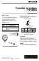
Installation Tools
The following tools will be useful during calibration check
and cover installation:
Part No. Description (Fig. 1)
305965 Gage, 0 to 30 psi (0 to 207 kPa)
CCT729A Gage Adapter for thermostats with
gage tap fitting
CCT735A Thermostat Tool
CCT729A
305965
CCT735A
Fig. 1. Thermostat installation tools.
INSTALLATION INSTRUCTIONS
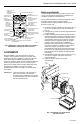
Remote Restrictors
When remote restrictors are required, (one pipe TP973)
select from Figure 2.
SEE CHART FOR BARB SIZE
A B
FILTER
INLET
ALL INLET BARBS
1/4 IN. (6 MM)
REMOTE RESTRICTORS
Part No. Orifice Body
Barb Size
in inches (MM)
14002913– Size in inches Color A B
–001* 0.005 Blue 1/4 (6)
5/32 (4)
–004 0.005 Blue 5/32 (4)
5/32 (4)
* One Barb Cap 14003567-001 Furnished with Restrictor
C3931-1
Fig. 2. Remote restrictors.
Piping
Use 5/32-in. O.D. polyethylene tubing. Connect main and
branch lines to the backplate, connecting main to the left
side barb fitting as viewed from the back and branch to the
right side barb. Leave the third (lower) fitting open, except
for a three-pipe TP971 Thermostat.
Mounting
See Figure 3. If mounting on other than a hollow wall, see
Installation Instructions 95-5597.
®U.S. Registered Trademark
Copyright © 1999 Honeywell Inc. • • All Rights Reserved
95-7478EF