TP970-72, TP970-74, TP9600, and TP9630 Pneumatic Sensors, Humidistats, and Thermostats INSTALLATION INSTRUCTIONS Contents INTRODUCTION ............................................................................................................................ 2 BEFORE INSTALLATION ............................................................................................................................ 2 Tools and Accessories .............................................................................
TP970-72, TP970-74, TP9600, AND PNEUMATIC SENSORS, HUMIDISTATS, AND THERMOSTATS INTRODUCTION The BEFORE INSTALLATION section shows tools and accessories used during installation and calibration, dimensions of major accessories, and procedures for preparing thermostat and humidistat covers. The INSTALLATION section shows how to install thermostats, humidistats, sensors, and fittings and shows connections for one- and two-pipe applications.
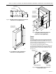
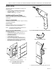
TP970-72, TP970-74, TP9600, AND TP9630 PNEUMATIC SENSORS, HUMIDISTATS, AND THERMOSTATS 1/2 (13) PROTECTIVE SLEEVE FOR BORE REPLACEMENT PROTECTIVE SLEEVES ARE AVAILABLE. ORDER CCT691A. REMOVABLE WEB (CUT AWAY WITH POCKET KNIFE) THERMOSTAT STEP/BORING TOOL 3-17/32 (90) CORDLESS DRILL ! 2-5/16 (59) ! WARNING TO AVOID BODILY INJURY AND PROTECT BORE, LEAVE PROTECTIVE SLEEVE ON STEP/BORING TOOL EXCEPT WHEN DRILLING WITH BORE. C3153 C3152 Fig. 6.
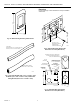
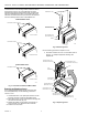
TP970-72, TP970-74, TP9600, AND PNEUMATIC SENSORS, HUMIDISTATS, AND THERMOSTATS Dimensions Figures 9 through 13 show dimensions of major installation accessories. 4-1/2 (115) 4-5/8 (117) 2-3/4 (70) 2-7/8 (73) C5532 2-1/4 (57) Fig. 7A. Wall Plate Bag Assembly 14002136-004. 1-11/16 (43) NO. 6-32 X 1/2 IN. MOUNTING SCREW (2) PROVIDED WITH SHALLOW WALLPLATE TWIN TUBE AK3240 (5/32 IN. O.D. X 0.030 IN. WALL) OR AK3241 (1/4 IN. O.D. X 0.040 IN. WALL) C3180 Fig. 9.
TP970-72, TP970-74, TP9600, AND TP9630 PNEUMATIC SENSORS, HUMIDISTATS, AND THERMOSTATS 1 IN. (25 MM) OFFSET FOR BOX EXTENSION PLATE 2 IN. (51 MM) OFFSET FOR BOX STUD-MOUNTED STAT PLATE (ALIGN OVER ELECTRICAL BOX) 1-1/2 (38) 1-7/16 (37) 3-1/16 (78) 3-15/16 (100) NO. 6-32 X 1/2 IN. MOUNTING SCREW (2) PROVIDED WITH STUD-MOUNTED STAT PLATE C3179 Fig. 11. Deep Wall Box Mounting Bracket 14001354-001 Dimensions in Inches (Millimeters).
TP970-72, TP970-74, TP9600, AND PNEUMATIC SENSORS, HUMIDISTATS, AND THERMOSTATS To determine the cover mounting method, look at the holes at the top of the cover (Fig. 15). If the setscrews are raised against the back pair of slots (toward the wall), the setscrews are in the backplate and the stat is a conventional stat. If the setscrews are raised into the front pair of holes, the setscrews are in the stat body and the stat is a Quick-Mount stat.
TP970-72, TP970-74, TP9600, AND TP9630 PNEUMATIC SENSORS, HUMIDISTATS, AND THERMOSTATS 2. Swing cover up and over stat. 3. Place Allen wrench end of Thermostat Tool through setscrew slot and into setscrew. 4. Rotate Thermostat Tool counterclockwise until setscrew holds cover securely onto stat backplate (conventional stat) or stat body (Quick-Mount stat). Repeat for other setscrew.
TP970-72, TP970-74, TP9600, AND PNEUMATIC SENSORS, HUMIDISTATS, AND THERMOSTATS Painting Cover after Window is Installed Order the following equipment: — Cover Assembly 14004407-XXX (select from HP970 and TP970 Series Standard Covers and Accessories Spec Data 77-1003) — Paint Mask 14002193-001 — DAY/AUTO Cover Insert 14004437-002 (optional) — Setpoint Cover Insert 14004438-002 (optional) COVER 90 WINDOW CURVED FOR INSTALLATION 80 1.
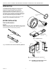
TP970-72, TP970-74, TP9600, AND TP9630 PNEUMATIC SENSORS, HUMIDISTATS, AND THERMOSTATS INSTALLATION TEK DRILL ADAPTER SCREWDRIVER This section categorizes stat installation according to the following factors: — Location of tubing: recessed or surface-mounted — Type of wall: hollow-core studded, block or brick, concrete, or mullion — Condition of wall: rough-in or finished Installation with Recessed Tubing Examples of installations with recessed tubing include: hollow-core stud walls, block or brick wall
TP970-72, TP970-74, TP9600, AND PNEUMATIC SENSORS, HUMIDISTATS, AND THERMOSTATS HORIZONTAL MOUNTING TO HORIZONTAL STUD HORIZONTAL MOUNTING TO VERTICAL STUD OR VERTICAL MOUNTING TO HORIZONTAL STUD OR VERTICAL MOUNTING TO VERTICAL STUD STUD MOUNT BOX CLIP MOUNTING TO METAL STUD (REQUIRES STUD MOUNT BOX CLIP CCT2642) TEK SCREW (2) EXTENSION PLATE NOTE: TO ATTACH STUD-MOUNTED STAT PLATE TO EXTENSION PLATE: SHEET METAL SCREW (2) A. FIT TWO BUTTONS ON EXTENSION PLATE INTO SLOTS ON STUD-MOUNTED STAT PLATE.
TP970-72, TP970-74, TP9600, AND TP9630 PNEUMATIC SENSORS, HUMIDISTATS, AND THERMOSTATS TUBING STUD-MOUNTED STAT PLATE STUD MOUNTED STAT PLATE TAB STAT BACKPLATE C3934 C3936 3. Fish tubing through Stud-Mounted Stat Plate. Anchor tubing in upper-right or lower-left corner of Plate by crimping Plate tab with pliers. 5. Hook keyhole slots of stat backplate over backed-out screws on Stud-Mounted Stat Plate. Level stat backplate and tighten screws. TUBING STAT BACKPLATE STAT BACKPLATE STAT C3935 4.
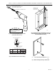
TP970-72, TP970-74, TP9600, AND PNEUMATIC SENSORS, HUMIDISTATS, AND THERMOSTATS Mounting to Stud with Deep Wall Box Mounting to a stud using a Deep Wall Box requires the following equipment: — Deep Wall Box Assembly 14001492-001 (includes two pipe plastic cable assembly, see Fig.
TP970-72, TP970-74, TP9600, AND TP9630 PNEUMATIC SENSORS, HUMIDISTATS, AND THERMOSTATS DEEP WALL BOX TEK DRILL ADAPTER SCREWDRIVER MOUNTING BRACKET NO. 8–32 X 1/4 IN. SCREW NO. 6–32 X 1/2 IN. SCREW (2) PROVIDED CORDLESS DRILL DEEP WALL BOX NO. 8–32 X 1/4 IN. SCREW C3167 Fig. 25. TEK Drill Adapter Screwdriver and Cordless Drill. MOUNTING BRACKET 1 (25) 3/4 (19) NO. 8–32 C3566 2. If offset from stud is required (e.g.
TP970-72, TP970-74, TP9600, AND PNEUMATIC SENSORS, HUMIDISTATS, AND THERMOSTATS STUD CABLE ASSEMBLY BARB COUPLINGS PROTECTOR CAP DEEP WALL BOX PLASTIC CABLE ASSEMBLY 8 FT (2.5 M) NO. 8 x 2 IN. SHEET METAL SCREWS OR 6d 2 IN. (51 MM) NAILS MOUNTING DEEP WALL BOX DIRECTLY TO STUD FITTING FINDER (IF WALL IS TO BE PLASTERED) NO. 8 x 1/2 IN. TEK SCREW UNIVERSAL STRAP C3561 4. Remove protector cap from Cable Assembly. Attach tubing to Cable with 5/32 x 1/4 in. or 5/32 x 5/32 in. Barb Couplings.
TP970-72, TP970-74, TP9600, AND TP9630 PNEUMATIC SENSORS, HUMIDISTATS, AND THERMOSTATS SETSCREWS STAT BACKPLATE STAT DEEP WALL BOX STAT BACKPLATE TAB (2) KEYHOLE SLOTS C3587 COVER 6. Back screws out of Deep Wall Box. Hook stat backplate keyhole slots onto backed-out screws. Level stat backplate and tighten screws. SETSCREW SLOTS C4115 8. Hook slots on stat cover over bottom tabs on stat backplate. Swing stat cover up and over stat.
TP970-72, TP970-74, TP9600, AND PNEUMATIC SENSORS, HUMIDISTATS, AND THERMOSTATS STUD MOUNT BOX CLIP (FOR STANDARD UTILITY CONDUIT BOX) STANDARD ELECTRICAL BOX 4 X 4 X 2-1/8 IN. (102 X 102 X 54 MM) STANDARD UTILITY CONDUIT BOX 4 X 2-1/8 X 1-7/8 IN. (102 X 55 X 48 MM) C3938 MFS CLIP (FOR STANDARD 4 X 4 ELECTRICAL BOX) Fig. 27. Standard Utility Conduit Box and Standard 4 x 4 in. Electrical Box. C3182 MAIN Fig. 29. Stud Mount Box Clip and MFS Clip.
TP970-72, TP970-74, TP9600, AND TP9630 PNEUMATIC SENSORS, HUMIDISTATS, AND THERMOSTATS CABLE ASSEMBLY STANDARD UTILITY CONDUIT BOX BUSHING PUSH BUSHING INTO KNOCKOUT NO. 10 X 3 PAN HEAD SHEET METAL SCREWS OR 6d 2 IN. (64 MM) NAILS MOUNTING STANDARD UTILITY CONDUIT BOX DIRECTLY TO STUD OR STANDARD UTILITY CONDUIT BOX 1/2 IN. EMT CONDUIT STUD MOUNT BOX CLIP 1/2 IN. TW SETSCREW CONNECTOR MOUNTING STANDARD UTILITY CONDUIT BOX TO STUD USING STUD MOUNT BOX CLIP STANDARD 4 x 4 ELECTRICAL BOX C3188 3.
TP970-72, TP970-74, TP9600, AND PNEUMATIC SENSORS, HUMIDISTATS, AND THERMOSTATS TUBING BARB COUPLINGS CABLE ASSEMBLY STANDARD UTILITY CONDUIT BOX STANDOFF RING (EARS BROKEN OFF) OR OR TUBING CONDUIT STANDARD 4 x 4 ELECTRICAL BOX STANDOFF RING IF WALL IS TO BE PLASTERED: C3189 STANDOFF RING 4. Remove protector cap from Cable Assembly and attach plastic tubing to Cable Assembly with 5/32 x 1/4 in. or 5/32 x 5/32 in. Barb Couplings. or Run plastic tubing through conduit. FITTING FINDER C3940 5.
TP970-72, TP970-74, TP9600, AND TP9630 PNEUMATIC SENSORS, HUMIDISTATS, AND THERMOSTATS STANDOFF RING IN WALL TUBING STAT BACKPLATE STAT BACKPLATE STAT C3579 C3592 8. Mount stat onto stat backplate. 6. After drywall or plaster is up, remove elbow from end of Cable Assembly, if used. Connect tubing to barbs on stat backplate. SETSCREWS STAT BACKPLATE STAT STANDOFF RING IN WALL STAT BACKPLATE TAB (2) KEYHOLE SLOTS COVER SETSCREW SLOTS C4117 C3586 9.
TP970-72, TP970-74, TP9600, AND PNEUMATIC SENSORS, HUMIDISTATS, AND THERMOSTATS Mounting to Lath Mounting to lath requires the following equipment: — Shallow Wall Plate Assembly 14001615-001/-002 or 14001616-001/-002 (Fig. 30). Includes the following: • Shallow Wall Plate 14001614-001 • Plaster Ring 14001609-001 • Fitting Finder 14000706-001 NOTE: — — — — — TAPE MEASURE Shallow Wall Plate Assembly 14001615-001 (one pipe) or -002 (two pipe) has copper tubing.
TP970-72, TP970-74, TP9600, AND TP9630 PNEUMATIC SENSORS, HUMIDISTATS, AND THERMOSTATS TUBING BARB COUPLINGS SHALLOW WALL PLATE SHALLOW WALL PLATE TUBING AND TWIN ELBOW ASSEMBLY BREAKOUT TAB PLASTER RING SCREWS PROVIDED WITH SHALLOW WALL PLATE C3948 5. Remove break-out tab from top of Plaster Ring. Push Plaster Ring onto Shallow Wall Plate brackets and lower screw receptacle. Attach Plaster Ring to Shallow Wall Plate with screws provided. 3.
TP970-72, TP970-74, TP9600, AND PNEUMATIC SENSORS, HUMIDISTATS, AND THERMOSTATS STAT BACKPLATE TWIN ELBOW CONNECTOR STAT BACKPLATE PLASTER RING IN WALL C3595 STAT C3578 7. After plaster is up, remove Fitting Finder from Plaster Ring. Remove protector from end of tubing, leaving Twin Elbow Connector. Connect Twin Elbow Connector to barbs on stat backplate. 9. Mount Stat to stat backplate.
TP970-72, TP970-74, TP9600, AND TP9630 PNEUMATIC SENSORS, HUMIDISTATS, AND THERMOSTATS Finished Wall Installation In a finished wall installation, the studs are covered with drywall or plaster and the tubing is behind the wall. Finished wall installation is done with a Quick-Mount Thermostat, anchors, or a Shallow Wall Plate. WALL Quick-Mount Thermostat Installing a Quick-Mount Thermostat requires the following tools: — Tape Measure CCT422 (Fig. 31) — Thermostat Mounting Guide Tool CCT690 (Fig.
TP970-72, TP970-74, TP9600, AND PNEUMATIC SENSORS, HUMIDISTATS, AND THERMOSTATS ANCHORS TWIN TUBE WIRE HOOK BARBS FISH CHAIN BACKPLATE ASSEMBLY C3175 BACKPLATE ASSEMBLY CONE 3. Use Fish Chain to fish tubing through center hole. C3942 5. Cut tubing. Use cone on Backplate Assembly to flare cut ends of tubing. Connect tubing to barbs on Backplate Assembly. BACKPLATE ASSEMBLY THERMOSTAT AND COVER ASSEMBLY PACKING SHELL C3941 BACKPLATE ASSEMBLY 4. Remove Backplate Assembly from packing shell.
TP970-72, TP970-74, TP9600, AND TP9630 PNEUMATIC SENSORS, HUMIDISTATS, AND THERMOSTATS PHILLIPS END BACKPLATE ASSEMBLY THERMOSTAT STEP/BORING TOOL SHIPPING STOP(S) C3178 CORDLESS DRILL 9. Remove shipping stop(s) from Thermostat and Cover Assembly. Place packing shell and shipping stop(s) back in carton. C3183 7. Hold Backplate Assembly to appear plumb. With protective sleeve over bore of Thermostat Step/Boring Tool, drive anchors with Phillips end of Tool.
TP970-72, TP970-74, TP9600, AND PNEUMATIC SENSORS, HUMIDISTATS, AND THERMOSTATS Anchors Drywall installation with anchors requires the following equipment: — Tape Measure CCT422 (Fig. 33) — Thermostat Mounting Guide Tool CCT690 (Fig. 33) — Cordless Drill CCT713 (Fig. 34) — Thermostat Step/Boring Tool CCT691 (Fig.
TP970-72, TP970-74, TP9600, AND TP9630 PNEUMATIC SENSORS, HUMIDISTATS, AND THERMOSTATS TWIN TUBE WIRE HOOK TUBING STAT BACKPLATE FISH CHAIN M3944 5. Cut tubing and connect to barbs on stat backplate. C3175 3. Use Fish Chain to fish tubing through center hole. PHILLIPS END STAT BACKPLATE MOLLY ANCHORS ANCHOR (2) STAT BACKPLATE KEYHOLE SLOTS C3943 4. Push Molly anchor heads through stat backplate keyhole slots. Tighten anchors slightly to secure them to stat backplate.
TP970-72, TP970-74, TP9600, AND PNEUMATIC SENSORS, HUMIDISTATS, AND THERMOSTATS Block or Brick Wall STAT BACKPLATE A stat should be mounted according to the steps shown in ROUGH-IN INSTALLATION. Use the procedure in FINISHED WALL INSTALLATION only if the stat cannot be roughed in as part of the wall. If the wall is to be plastered, see INSTALLATION WITH SURFACE-MOUNTED TUBING. Rough-In Installation Rough-in is done by the mason as the wall is laid.
TP970-72, TP970-74, TP9600, AND TP9630 PNEUMATIC SENSORS, HUMIDISTATS, AND THERMOSTATS MAIN CABLE ASSEMBLY SWITCH BARB TEE PUSH BUSHING INTO KNOCKOUT BRANCH THREE-PIPE ASSEMBLY MAIN BARB CAP BRANCH ONE-PIPE ASSEMBLY DEEP WALL BOX BUSHING MAIN ELBOW BRANCH TWO-PIPE ASSEMBLY OR PROTECTOR CAP CABLE ASSEMBLY BARB COUPLINGS FOR PLASTIC TUBING 1/2 IN. EMT CONDUIT 1/2 IN. TW SETSCREW CONNECTOR OR DEEP WALL BOX 1/2 IN. EMT CONDUIT 1/2 IN. TW SETSCREW CONNECTOR C3563 C3564 Fig. 36.
TP970-72, TP970-74, TP9600, AND PNEUMATIC SENSORS, HUMIDISTATS, AND THERMOSTATS TUBING HOLLOW BLCOK OR BRICK WALL BARB COUPLINGS DEEP WALL BOX CABLE ASSEMBLY OR C4101 TUBING 3. Measure approximate location of stat. Hang or position Deep Wall Box at measured location. CONDUIT PLASTIC CABLE CONDUIT C3565 2. Remove protector cap from Cable Assembly and attach plastic tubing to Cable Assembly with 5/32 x 1/4 in. or 5/32 x 5/32 in. Barb Couplings. or Run plastic tubing through conduit.
TP970-72, TP970-74, TP9600, AND TP9630 PNEUMATIC SENSORS, HUMIDISTATS, AND THERMOSTATS 7. Mount stat to stat backplate. 8. Hook slots on stat cover over bottom tabs on stat backplate. Swing stat cover up and over stat. Use Thermostat Tool to raise stat backplate setscrews into setscrew slots on top of cover. DEEP WALL BOX IN BLOCK BRICK WALL Finished Wall Installation This section describes finished wall installation with tubing recessed in the openings inside the block or brick.
TP970-72, TP970-74, TP9600, AND PNEUMATIC SENSORS, HUMIDISTATS, AND THERMOSTATS MASONRY DRILL MASONRY DRILL (7/8 -IN. BIT) HAMMER DRILL C3191 HAMMER DRILL Fig. 38. Hammer Drill and 3/16-in. or 7/8-in. Masonry Drill. C3196 2. Use 7/8-in. Masonry Drill and Hammer Drill to Drill 7/8-in. (22.2-mm) center hole. TAPE MEASURE THERMOSTAT MOUNTING GUIDE TOOL C3195 1. Measure approximate stat location on wall.
TP970-72, TP970-74, TP9600, AND TP9630 PNEUMATIC SENSORS, HUMIDISTATS, AND THERMOSTATS MASONRY DRILL (3/16-IN. BIT) 3/16 IN. (4.8 MM) PLASTIC SCREW ANCHOR (2) PLASTIC SCEW ANCHOR (2) NO. 8 SHEET METAL SCREWS (2) HAMMER DRILL C3199 3. Use 3/16-in. Masonry Drill to drill 3/16-in. (4.8-mm) top and bottom holes. C3197 5. Knot tubing. Tap 3/4 in. Plastic Screw Anchors into top and bottom holes. Screw No. 8 sheet metal screws partway into Plastic Screw Anchors.
TP970-72, TP970-74, TP9600, AND PNEUMATIC SENSORS, HUMIDISTATS, AND THERMOSTATS 9. Hook slots on stat cover over bottom tabs on stat backplate. Swing stat cover up and over stat. Use Thermostat Tool to raise stat backplate setscrews into setscrew slots on top of cover. Concrete Pour Mounting in preparation for a concrete pour requires the following equipment: — Deep Wall Box 14001355-001 (Fig. 39) — One of the following (Fig.
TP970-72, TP970-74, TP9600, AND TP9630 PNEUMATIC SENSORS, HUMIDISTATS, AND THERMOSTATS MAIN STEEL REINFORCEMENT ROD SWITCH BARB TEE BRANCH THREE-PIPE ASSEMBLY MAIN BARB CAP BRANCH TAPE MEASURE ONE-PIPE ASSEMBLY BUSHING MAIN ELBOW BRANCH TWO-PIPE ASSEMBLY PROTECTOR CAP CABLE ASSEMBLY BARB COUPLINGS FOR PLASTIC TUBING C3164 1. Measure and mark stat location on steel reinforcement rods. OR 1/2 IN. EMT CONDUIT 1/2 IN. TW SETSCREW CONNECTOR C3563 Fig. 40.
TP970-72, TP970-74, TP9600, AND PNEUMATIC SENSORS, HUMIDISTATS, AND THERMOSTATS CABLE ASSEMBLY TUBING BARB COUPLINGS PUSH BUSHING INTO KNOCKOUT CABLE ASSEMBLY DEEP WALL BOX OR OR TUBING 1/2 IN. EMT CONDUIT 1/2 IN. TW SETSCREW CONNECTOR CONDUIT DEEP WALL BOX C3565 C3564 3. Run plastic tubing through conduit, or remove protector cap from Cable Assembly and attach plastic tubing to Cable Assembly with 5/32 x 1/4 in. or 5/32 x 5/32 in. Barb Couplings. 2.
TP970-72, TP970-74, TP9600, AND TP9630 PNEUMATIC SENSORS, HUMIDISTATS, AND THERMOSTATS SOFT COPPER TIE WIRE OR PLASTIC COVERED WIRE TIE STEEL REINFORCEMENT ROD TAPED DEEP WALL BOX POSITION SO THAT FRONT OF BOX WILL BE FLUSH WITH WALL DEEP WALL BOX STAT BACKPLATE C3585 7. Back screws out of Deep Wall Box. Hook stat backplate keyhole slots onto backed-out screws. Level stat backplate and tighten screws. C3165 5.
TP970-72, TP970-74, TP9600, AND PNEUMATIC SENSORS, HUMIDISTATS, AND THERMOSTATS SETSCREWS STAT BACKPLATE UNI-BIT 1/8 IN. HIGH SPEED DRILL BIT STAT CORDLESS DRILL TAB (2) COVER C3168 C4119 SETSCREW SLOTS Fig. 42. Unit-Bit, 1/8 in. High-Speed Drill Bit, and Cordless Drill. 9. Hook slots on stat cover over bottom tabs on stat backplate. Swing stat cover up and over stat. Use Thermostat Tool to raise stat backplate setscrews into setscrew slots on top of cover.
TP970-72, TP970-74, TP9600, AND TP9630 PNEUMATIC SENSORS, HUMIDISTATS, AND THERMOSTATS WIRE HOOK 7/8 IN. (22 MM) UNI-BIT CORDLESS DRILL FISH CHAIN C3193 C4103 4. Use Fish Chain to fish tubing through center hole. 2. Use Uni-Bit and Cordless Drill to drill 7/8-in. (22-mm) center hole. STAT BACKPLATE TUBING 1/8 IN. (3.2 MM) 1/8 IN. HIGH SPEED DRILL BIT C4106 5. Attach tubing to barbs on stat backplate. CORDLESS DRILL C3194 3. Use 1/8 in. High-Speed Drill Bit to drill 1/8-in. (3.
TP970-72, TP970-74, TP9600, AND PNEUMATIC SENSORS, HUMIDISTATS, AND THERMOSTATS SETSCREWS STAT BACKPLATE STAT BACKPLATE NO. 8 x 3/4 SHEET METAL SCREW (2) STAT C4105 6. Position stat backplate against mullion. Level stat backplate. Screw No. 8 x 3/4 in. Sheet Metal Screws through stat backplate keyhole slots into mullion. TAB (2) COVER SETSCREW SLOTS C4111 8. Hook slots on stat cover over bottom tabs on stat backplate. Swing stat cover up and over stat.
TP970-72, TP970-74, TP9600, AND TP9630 PNEUMATIC SENSORS, HUMIDISTATS, AND THERMOSTATS SHALLOW WALL PLATE BOTH ENDS ARE REMOVABLE PROTECTOR CAP THERMOSTAT STEP/BORING TOOL 8 FT (2.5 M)TUBING AND TWIN ELBOW ASSEMBLY 1 PLASTER RING MASONARY DRILL CORDLESS HAMMER DRILL 1 FITTING FINDER PRESS TO SNAP IN PLACE 1 AVAILABLE SEPARATELY C3597 Fig. 43. Shallow Wall Plate Assembly. C3190 1/2 (13) Fig. 45. Masonry Drill, Thermostat Step/Boring Tool, and Cordless Hammer Drill.
TP970-72, TP970-74, TP9600, AND PNEUMATIC SENSORS, HUMIDISTATS, AND THERMOSTATS 3. If wall is: a. Block, brick, or concrete, use Cordless Hammer Drill and Masonry Drill to drill 3/16-in. (4.8-mm) holes where marked. Tap Plastic Screw Anchors into holes. STEP THERMOSTAT STEP/BORING TOOL SAMPLE ANCHOR LOCATIONS CORDLESS DRILL SHALLOW WALL PLATE (ENDS BROKEN OFF) C3184 2. Break off ends of Shallow Wall Plate. Center Shallow Wall Plate over mark on wall.
TP970-72, TP970-74, TP9600, AND TP9630 PNEUMATIC SENSORS, HUMIDISTATS, AND THERMOSTATS TUBING AND TWIN ELBOW ASSEMBLY PHILLIPS END STRAIN RELIEF THERMOSTAT STEP/BORING TOOL CORDLESS HAMMER DRILL SHALLOW WALL PLATE 6. Remove screw from Shallow Wall Plate upper screw receptacle. Push strain relief of Tubing and Twin Elbow Assembly onto screw receptacle. Replace screw, leaving it slightly backed out. Back out bottom screw. SHALLOW WALL PLATE MOLLY ANCHORS (2) C3947 b.
TP970-72, TP970-74, TP9600, AND PNEUMATIC SENSORS, HUMIDISTATS, AND THERMOSTATS TUBING AND TWIN ELBOW ASSEMBLY STAT BACKPLATE STAT BACKPLATE STAT C3593 C3581 8. Connect Twin Elbow Connector to barbs on stat backplate. 10. Mount stat onto stat backplate. SETSCREWS STAT BACKPLATE BACKED-OUT SCREW (2) STAT STAT BACKPLATE KEYHOLE SLOTS C3594 TAB (2) 9. Hook keyhole slots of stat backplate over backed-out screws. Level stat backplate and tighten screws. COVER SETSCREW SLOTS C4113 11.
TP970-72, TP970-74, TP9600, AND TP9630 PNEUMATIC SENSORS, HUMIDISTATS, AND THERMOSTATS Piping Figures 46 and 47 show typical one-pipe and two-pipe applications. STAT THERMOSTAT TOOL M VALVE TEST THERMOMETER 100 80 60 40 20 C3159 15 Fig. 46. Typical One-Pipe Application. 20 180 200 220 0 25 10 5 120140 160 30 STAT 0 GAGE PORT NEEDLE M B GAGE M VALVE DIGITAL RELATIVE HUMIDITY INDICATOR PEN C3160 C3929 Fig. 47. Typical Two-Pipe Application. Fig. 48.
TP970-72, TP970-74, TP9600, AND PNEUMATIC SENSORS, HUMIDISTATS, AND THERMOSTATS 5. Turn setpoint indicator up slowly. 6. If humidistat bleeds off at ±3 percent rh of measured humidity, no further calibration is necessary. Remove Gage and replace humidistat cover. 7. If humidistat does not operate as described in Step 6, recalibrate humidistat (see RECALIBRATION). Figure 49 shows humidistat components.
TP970-72, TP970-74, TP9600, AND TP9630 PNEUMATIC SENSORS, HUMIDISTATS, AND THERMOSTATS Throttling Range Adjustment Output Pressure in psi (kPa) Range: 15 to 75% % rh 15 to 85% HP971A1024* 1. Use Thermostat Tool to remove cover. Assemble Gage and Gage Port Needle. 2. Insert Gage Port Needle in thermostat gage tap. 3. Slide throttling range (TR) adjustment to desired position on TR scale. 4.
TP970-72, TP970-74, TP9600, AND PNEUMATIC SENSORS, HUMIDISTATS, AND THERMOSTATS General Procedure (All Thermostats) 1. Use Test Thermometer to measure actual temperature of space. 2. Use Thermostat Tool to remove thermostat cover. Assemble Gage and Gage Port Needle. 3. Insert Gage Port Needle into thermostat gage tap. 4. Turn setpoint adjustment until setpoint indicator reads measured room temperature. 5. Proceed to appropriate section following. TP970 and TP9600 Thermostats 1.