
Install Instructions
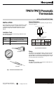
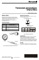


TP970-TP973 PNEUMATIC THERMOSTATS
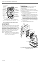
THROTTLING RANGE
Throttling Range
Throttling ranges (TR) are factory set at 4F (2K) and
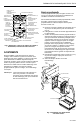
ANTIHUM
should not require any change under normal
SPRING (2)
operating conditions.
THROTTLING
RANGE
If a change in throttling range is necessary, reset the
ADJUSTMENT (2)
BOBBIN
(NITE/WINTER)
throttling range to the values specified on the job drawings.
Use the following procedures:
TEMPERATURE
SETPOINT
INDICATOR
1. Remove stat cover and install 0 to 30 psi (0 to 207
kPa) gage in gage tap (Fig. 4)
SETPOINT
2. Slide the TR indicator to the desired position on the
INDICATOR
SCREW
TR scale.
(NITE/WINTER)
3. Mechanically check the TR by moving setpoint lever
SETPOINT DIAL
STOPS
to determine the difference in setpoint indication
when the branchline pressure reads 3 psi (21 kPa)
and 13 psi (91 kPa). (It may be necessary to turn the
calibration screw to adjust TR into the stat range.)
(NITE/WINTER)
4. Reset TR to within ±2F (±1K) of required setting for
C3946-3
accurate control.
5. Follow RECALIBRATION procedures.
Fig. 3. Installing TP970-TP973 without wall box.
ADJUSTMENTS
After installation, set the thermostat to the desired setpoint
and let the system operate long enough to stabilize. The
length of time required for stabilization depends on system
response time. This could be only a few minutes or as long
as several hours. Make certain that the system has
stabilized before checking calibration. If the temperature
stabilizes within one-half of the throttling range of the
setpoint, no calibration is required.
NOTE: All thermostats are accurately factory calibrated
and should require only a calibration (bleed-off)
check to ensure correct operation.
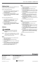
7060 80 90
THERMOMETER
CALIBRATION
INDICATOR
CALIBRATION
(DAY/SUMMER)
DAY/AUTO LEVER
(TP971 ONLY)
SETPOINT INDICATOR
ADJUSTMENT
5
5
5
6
7
SCALEPLATE
M
X
M
A
X
SCALE (2)
(DAY/SUMMER)
THROTTLING
PLATE (2)
GAGE TAP
NOTE: NOT ALL ADJUSTMENTS ARE ON ALL THERMOSTATS.
TEMPERATURE
SETTING
60
70
80
90
1-1/8
2-1/4
HOLLOW
WALL
1 INCH
HOLE
5/32 INCH
TUBING
COVER
STAT
BACKPLATE
C6398-1
Fig. 4. TP971 and TP972A2218 controls and indicators.
Front view—cover off.
95-7478EF
2