
Install Instructions
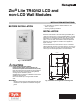
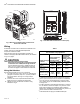
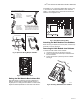
Table Of Contents

INSTALLATION INSTRUCTIONS
62-0467-05
Zio
®
Lite TR40/42 LCD and
non-LCD Wall Modules
BEFORE INSTALLATION
Fig. 1. LCD Wall Module.
CAUTION
Erratic System Operation Hazard.
Failure to follow proper wiring practices can
introduce disruptive electrical interference (noise).
Keep wiring at least one foot away from large inductive
loads such as motors line starters, lighting ballasts,
and large power distribution panels.
Shielded cable is required in installations where these
guidelines cannot be met.
Ground the shield only to the grounded controller
case.
IMPORTANT
All wiring must comply with local electrical codes and
ordinances or as specified on installation wiring dia-
grams.
— For information on Sylk bus distance limitations, see
Table 1 on page 2.
— All wiring is polarity insensitive.
INSTALLATION
Mount the wall module on an inside wall approximately 54 in.
(1372 mm) from the floor (or in the specified location), to allow
exposure to the average zone temperature. Do not mount the
wall module on an outside wall, on a wall containing water
pipes, or near air ducts. Avoid locations that are exposed to
discharge air from registers or radiation from appliances,
lights, or the sun.
The wall module can be mounted on a wall, on a standard
utility conduit box using No. 6 (3.5 mm) screws or on a 60 mm
wall outlet box (see Fig. 3). When mounting directly on a wall,
use the type of screws appropriate for the wall material.
Fig. 2. Subbase mounting holes and locking tabs.
M34633
3-11/64 (81)
4-41/64
(118)
3-1/4
(83)
2-3/8 (60)
2-3/8
(60)
2-3/8 (60)