
user manual

Configuration
90 UDA2182 Universal Dual Analyzer Product Manual January 2009
Accessing Auxiliary Menu
• Press
Setup
to display the Main menu.
• Use the
keys to select “Auxiliary” then press
Enter
to enter the sub-menu.
• Press
to highlight the desired menu selection then press
Enter
to display the
group of parameters.
Refer to “Section 6.4.1 – “General Rules for Editing”.
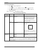
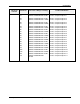
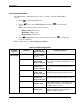
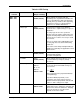
Table 6-12 Auxiliary Configuration
Sub-menu
selection
Parameter Selection or Range of Setting Parameter Definition
In A Source
In B Source
Any Analog Signal
See Table 6-3
Analog Signal Source – Process signal
to be monitored by the Alarm. Any
analog source such as PV, Temperature,
Pharma, Math, Function Generator,
Switch, PID, or Calculated Values*
* units of measure between the two input
boards must be similar
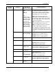
Switch 1
Switch 2
Select B
Any Digital Signal
See Table 6-4
Digital Signal Source when active will
select the B input source of the switch as
the output
Switch
InA
InB
Select B
If Select B is OFF then Switch Output = In A
If Select B is ON then Switch Output = In B
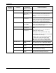
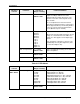
Source
None
Input 1 PV
Input 2 PV
PID 1 Out
PID 2 Out
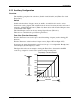
Function Generator selections have 2
input sources
(Input 1 PV and Input 2 PV).
Func Gen 1
Func Gen 2
ATTENTION
The X (n) value must be < X(n+1) value. Thus, if fewer than 11 breakpoints are needed,
be sure to configure any unneeded breakpoints with the same X and Y values used for the
previous breakpoint.