
user manual

Configuration
96 UDA2182 Universal Dual Analyzer Product Manual January 2009
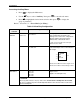
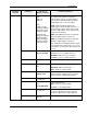
Sub-menu
selection
Parameter Selection or
Range of Setting
Parameter Definition
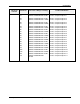
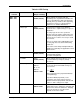
Bias
0.0 Default
-9999 to 99999
Bias that is applied to the Remote Setpoint.
RSP Select
Monitor (1 – 4)
Logic (1 – 4)
Digital In (1 – 2)
When this input is ON, the Remote Setpoint is
used. If set to None, the operator can select
the remote setpoint from the PID operator
display.
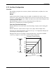
FF Source
Any Analog Signal
See Table 6-3
Feed Forward value that is applied to the
output. A change in the feed forward signal
input will result in a proportional change in the
output per the feed forward gain parameter.
FF Gain
1.000 (default)
0.1 to 1000.0
Feed Forward Gain used to calculate the
change in the PID output based upon a change
of the feed forward input signal.
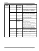
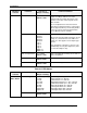
TRC Select
Any Digital Signal
See Table 6-4
TRV Select
Any Analog Signal
See Table 6-3
TRC (tracking control) – selects the tracking
mode
TRV (tracking value) – is the commanded
output value in percentage
(PID Output = TRV Input when TRC = ON)
When TRC is active, the front-panel display will
indicate TRC for the PID loop.
Variables can be connected to TRC and TRV
to allow remote control of the PID output.
TRC can be connected to a digital variable
TRV can be connected to an analog variable
Manual Permit
Enable (default)
Disable
Allows the operator to select Manual Operation
of the PID loop from the PID Operator Display
Auto Permit
Enable (default)
Disable
Allows the operator to select Auto Operation of
the PID loop from the PID Operator Display
LSP Permit
Enable (default)
Disable
Allows the operator to select the Local Setpoint
from the PID Operator Display
RSP Permit
Enable (default)
Disable
Allows the operator to select the Remote
Setpoint from the PID Operator Display