
user manual


Inputs and Outputs Wiring
116 UDA2182 Universal Dual Analyzer Product Manual January 2009
Conform to code
Instrument wiring should conform to regulations of the National Electrical Code.
Recommended maximum wire size
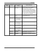
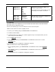
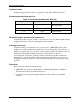
Table 7-1 Recommended Maximum Wire Size
Gage Number mm
2
Description
14 2.081 power, relays, and PE
(protective earth)
18 0.823 inputs
18 0.823 isolated outputs
Shielded wiring for locations with interference
In applications where plastic conduit or open wire trays are used, shielded milticonductor
22 gage (0.326 mm
2
) or heavier signal input wiring is required.
Avoiding interference
Instrument wiring is considered Level 1, per section 6.3 of IEEE STD. 518 for plant
facilities layout and instrumentation application. Level 1 wiring must not be run close to
higher level signals such as power lines or drive signals for phase fired SCR systems, etc.
Unprotected input wiring in high electrical noise environments is subject to
electromagnetic, electrostatic, and radio frequency interference pickup of sufficient
magnitude to overload input filters. The best instrument performance is obtained by
keeping the interfering signals out of the instruments altogether by using proper wiring
practices.
References
Refer to the following when wiring the unit.
• IEEE STD. 518, Guide for the Installation of Electrical Equipment to Minimize
Electrical Noise Inputs from External Sources.
• Appropriate wiring diagram supplied with electrode mounting or preamplifier
module.