
user manual


Inputs and Outputs Wiring
January 2009 UDA2182 Universal Dual Analyzer Product Manual 119
Table 7-2 Procedure for installing Input and Output wiring
Step Action
1
Go to Configuration setup to view the displays showing analog input, relay, and analog
output use. Note the assignments shown. You must wire the unit to match these
assignments in order for the analyzer to work as expected (See Section 6).
ATTENTION
Turn off the power to the analyzer.
More than one switch may be required to remove power.
2
With power off, open the case:
• Loosen the four captive screws on the front of the bezel.
• Grasp the bezel on the right side. Lift the bezel gently and swing the bezel open to the left.
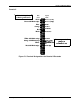
3
Refer to Figure 7-1 for the location of the terminal board retainer. Loosen the screws that
hold the retainer and slide the retainer left until the retainer tabs disengage from the terminal
boards.
4
Insert a screwdriver into the tab in the terminal board to be wired and pull out gently. Slide
the board half way out. There is a notch in the terminal board into which you can slide the
retainer tabs and hold the boards in place while wiring.
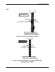
5
Connect the inputs from the electrode or cells to the terminals in accordance with the
configuration setup assignments. Refer to the wiring diagram provided with the electrode or
cell, and to Figure 7-2 through Figure 7-20
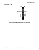
6
Analog outputs (In addition to the standard outputs, one more is available as an option). See
Option Board Wiring - Figure 7-20). Connect the outputs from the Analyzer terminals in
accordance with the configuration setup assignments. Refer to the wiring diagrams provided
with the field devices receiving the signals, and to Figure 7-2 through Figure 7-20.
7
If the relay outputs are to be used, leave the unit open and powered down. The relays can
be used for Time Proportioning Output, Pulse Frequency Output, and Digital Output control
as well as alarm annunciation. (In addition to the standard relays, two more are available as
an option. See Option Board Wiring - Figure 7-20). Connect the outputs from the Analyzer
terminals in accordance with the configuration setup assignments. Refer to the wiring
diagrams provided with the external device and to Figure 7-2 through Figure 7-20.
These relays can be programmed to de-energize or energize on alarm. Use the
Maintenance configuration setup to specify relay state. (NOTE 1)
CAUTION: Alarm circuits are not internally fused in the analyzer. Provision for fuses in
external circuits is recommended.
8
Slide the retainer to the left then slide the terminal board back into place. Slide retainer to
engage the tabs and tighten the screws.
9
Close the Bezel and secure four captive screws to a torque value of .20Nm (1.5 Lb-in).
Power up the unit.
Do not apply power until the bezel is closed.
Note 1: If set to de-energize on alarm, this means that when an alarm occurs (or the discrete control point
becomes active), the relay coil will be de-energized. The NC contacts will then be closed and the NO
contacts will be open. Conversely, during normal non-alarm operation (or when the control point is not
active) the NC contacts will be open, and the NO contacts will be closed. If de-energize on alarm is selected,
a power loss will force all relays to the same position as an alarm condition.