
user manual


Inputs and Outputs Wiring
120 UDA2182 Universal Dual Analyzer Product Manual January 2009
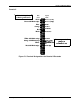
7.4 Direct pH/ORP Input Wiring Diagrams
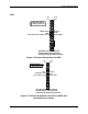
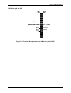
Durafet III
15
14
13
12
11
10
9
8
7
6
5
4
3
2
1
Signal
Name
Wire
Color
R
KO
res- (Low)
R
KO
res- (High)
Drain
Source
Substrate
Reference
Counter
RTH 3
rd
Wire
RTH Low
RTH High
EEGND
EEDATA
Green
Green with Black stripe
Blue
Orange
Red
Black
White with Black stripe
Orange with Black stripe
Red with Black stripe
White
Black with White stripe
Blue with Black stripe
Cable shield (yellow)
to chassis ground screw
Remove pre-wired
jumper at
terminals 5 & 6
15
14
13
12
11
10
9
8
7
6
5
4
3
2
1
15
14
13
12
11
10
9
8
7
6
5
4
3
2
1
Signal
Name
Wire
Color
R
KO
res- (Low)
R
KO
res- (High)
Drain
Source
Substrate
Reference
Counter
RTH 3
rd
Wire
RTH Low
RTH High
EEGND
EEDATA
Green
Green with Black stripe
Blue
Orange
Red
Black
White with Black stripe
Orange with Black stripe
Red with Black stripe
White
Black with White stripe
Blue with Black stripe
Cable shield (yellow)
to chassis ground screw
Remove pre-wired
jumper at
terminals 5 & 6
Figure 7-2 Terminal Designations for Durafet III Electrode