
user manual


Inputs and Outputs Wiring
January 2009 UDA2182 Universal Dual Analyzer Product Manual 135
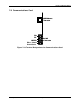
7.10 Option Card
15
14
13
12
11
10
9
8
7
6
5
4
3
2
1
Analog Output 3 (+)
Analog Output 3 (–)
Digital Input 1 (+)*
Relay Output 3 (N.O.)
Relay Output 3 (COM)
Relay Output 3 (N.C.)
Case (earth) Ground
Relay Output 4 (N.O.)
Relay Output 4 (COM)
Relay Output 4 (N.C.)
Case (earth) Ground
Digital Input 1 (–)*
Digital Input 2 (+)*
Digital Input 2 (–)*
Case (earth) Ground
* Contact Closure only
15
14
13
12
11
10
9
8
7
6
5
4
3
2
1
15
14
13
12
11
10
9
8
7
6
5
4
3
2
1
Analog Output 3 (+)
Analog Output 3 (–)
Digital Input 1 (+)*
Relay Output 3 (N.O.)
Relay Output 3 (COM)
Relay Output 3 (N.C.)
Case (earth) Ground
Relay Output 4 (N.O.)
Relay Output 4 (COM)
Relay Output 4 (N.C.)
Case (earth) Ground
Digital Input 1 (–)*
Digital Input 2 (+)*
Digital Input 2 (–)*
Case (earth) Ground
* Contact Closure only
Figure 7-20 Terminal Designations for Option Board