
user manual

Input Calibration
154 UDA2182 Universal Dual Analyzer Product Manual January 2009
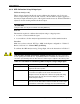
8.6.3 ORP Calibration Using Voltage Input
Calibrates Analyzer only
The procedure described in this sub-section calibrates the Analyzer only. It does not
involve compensating for electrode drift. Instead, a known millivolt signal is applied to
the analyzer input terminals in place of the signal from the electrode, and the UDA2182 is
adjusted so that its reading matches the known input.
ATTENTION
This procedure can only be used when measuring ORP only
Materials
The materials required to calibrate the Analyzer using a voltage input are:
• A source of a known millivolt signal.
• A screwdriver to fit the Analyzer input terminal screws and the terminal retainer.
Procedure
Make sure you have selected “PV Type –ORP” in the Inputs configuration – Table 6-5.
Refer to Section 6.4.1 –
General Rules for Editing.
To calibrate the ORP Analyzer using Voltage Input, follow the instructions in Table 8-7.
WARNING
This procedure should be performed by qualified personnel only. Disconnect the power
before opening the instrument case. A potentially lethal shock hazard exists inside the case if
the unit is opened while powered. More than one switch may be required to disconnect power.
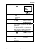
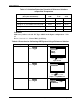
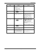
Table 8-7 Procedure for Calibrating ORP Analyzer Using Voltage Input
Step Action Screen
1
Turn off the power to the Analyzer. More than one switch may be
required to disconnect power.
2
With the power off open the case:
Loosen the four captive screws on the front of the bezel.
Grasp the bezel on the right side. Lift the bezel gently and swing
the bezel open to the left. (The bezel and display assembly is
mounted on pivot arms.)
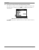
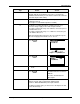
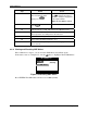
3
Refer to Figure 7-1 for the location of the terminal board retainer.
Loose the screws that hold the retainer and slide the retainer right
or left until the retainer tabs disengage from the terminal boards.