
user manual

Input Calibration
January 2009 UDA2182 Universal Dual Analyzer Product Manual 155
Step Action Screen
4
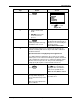
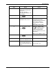
Insert a screwdriver into the tab in the terminal board to be wired
and pull. Slide the board half way out. There is a notch in the
terminal board into which you can slide the retainer tabs and hold
the boards in place while wiring.
5
Label and remove the input wiring from the input terminals.
Terminals 8 and 10.
(See Figure 7-6 Terminal Designations for ORP).
6
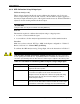
Feeding the test wiring through the conduit hole in the case,
connect a voltage supply to the 8 and 10 input terminals
• To apply a signal in the range 0 to 1600 mV, connect the plus to
8 and the minus to 10.
• To apply a signal in the range -1 to -1600 mV, connect the plus
to 10 and the minus to 8.
Slide the Input board back and close the case and power up the
unit. Do not apply power until the case is closed.
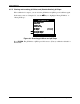
7
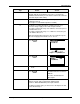
Press
Calibrate
PV INPUT CAL
In 1 pH/ORP Cal
In 2 Conduc Cal
PV INPUT CAL
In 1 pH/ORP Cal
In 2 Conduc Cal
Use
to select
Input 1 or 2 pH/ORP Cal
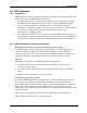
8
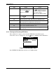
Press
Enter
IN 1 pH/ORP Cal
Sample Cal
ORP Offset
Reset ORP Offset
0.000
IN 1 pH/ORP Cal
Sample Cal
ORP Offset
Reset ORP Offset
0.000
9
• Put the unit in “Hold”
mode
10
Press
Enter
The display will show the
Oxidation Reduction Potential in
Millivolts.
The value should match the
Input signal.
11
Ignore the instructions to put the electrode in the reference
solution. Instead, apply an appropriate millivolt signal
(between –2000 and 2000 mV) to the input terminals.
To obtain a negative value, you must reverse the input to the unit
as described in Step 5.