
user manual

Input Calibration
January 2009 UDA2182 Universal Dual Analyzer Product Manual 173
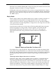
before the test was initiated. During this voltage sweep, the probe current is monitored and
the graph of current as a function of voltage is displayed.
If during the test the probe current rises above a factory-set upper limit, the bias voltage is
returned to its pre-test value at 25mV/sec and the test is terminated without completing the
full 1.0 Volt sweep. (The bias voltage test may also be terminated at any time by pressing
the “EXIT” button.)
Display Graph
Under normal conditions, the completed display shows a graph of current as a function of
voltage with the following features: from approximately 0 to 0.2 volts a fairly rapid
increase in current is observed; from approximately 0.2 to 0.8 volts, the current exhibits a
“flat” region where it is nearly independent of voltage and at some voltage above about 0.8
volts, the current rises quickly.
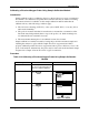
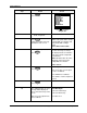
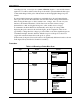
A typical current-voltage curve is shown below. The Sweep Bias millivoltage (along the
bottom of the graph) is a voltage from 0 -1V that is applied to perform the test. The
Operating Bias millivoltage is the current position of the cursor on the graph and
represents the current bias voltage. The horizontal axis numerals are in hundreds of
millivolts.
0.55V 80μA
0 0.2 0.4 0.6 0.8
μA 0
80
160
240
1V
0.55V 80μA
0 0.2 0.4 0.6 0.8
μA 0
80
160
240
1V
Figure 8-5 Display of Probe Bias Test Done in Air
Note that the curve is quite flat at 0.55V. This means that even rather large changes in the
probe current-voltage characteristic do not affect the current (and, thus, probe sensitivity)
at 0.55V. In general, the curve formed by decreasing voltage is not identical to that formed
by increasing voltage. This hysteresis is a function of the voltage scan rate and may be
ignored.
The interpretation of figure shown above is as follows:
As the bias voltage of the oxygen-consuming electrode (relative to an internal reference
electrode) is increased, there is an initial increase in current as more and more of the
oxygen that approaches the electrode is reacted. However, at about 0.2V, the current stops
rising and a flat region, independent of voltage, is observed. It is in this region that probe
current is determined by oxygen mass transport limitation. Increasing the voltage cannot
increase the current because oxygen movement is diffusion limited. Finally, at a voltage