
user manual

Input Calibration
174 UDA2182 Universal Dual Analyzer Product Manual January 2009
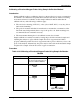
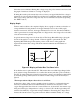
exceeding 0.8 volts, a second process (water reduction) begins to occur and the current
again rises. To achieve stable results, the probe should be operated within the flat region
so that small changes in the probe characteristics result in negligible changes in probe
current.
In some industrial wastewater applications, particularly those in petroleum refineries,
active gases dissolved in the wastewater can cause this current-voltage characteristic to
shift, moving the flat region to other, usually lower, voltages. Also, in some very rare
instances, the chemical treatment of boiler water can cause this current-voltage
characteristic to shift, moving the flat region to other, usually lower, voltages.
To summarize, the Probe Bias Test automatically varies the probe voltage while
displaying the probe current as shown in the figure. At the completion of the test an
opportunity to change the bias voltage is provided. Thus, even where significant gaseous
contamination might otherwise interfere with the response of the probe to dissolved
oxygen, this advanced feature allows the probe to operate.
(If the results of the probe bias test should ever be significantly different from those shown
in the figure, Honeywell Service should be consulted.)
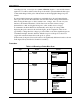
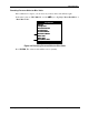
Procedure
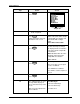
Table 8-14 Running a Probe Bias Scan
Step Action Screen
1
Press
Calibrate
CALIBRATION
Input Temp Cal
Output Cal
Cal History
Input PV Cal
CALIBRATION
Input Temp Cal
Output Cal
Cal History
Input PV Cal
2
Press
Enter
PV INPUT CAL
In 1 DO Cal
PV INPUT CAL
In 1 DO Cal
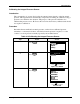
Use
to select
Input 1 or 2 DO Cal
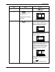
3
Press
Enter
IN1 DO CAL
Sample Cal
Air Cal
Pressure Cal
Bias Volts
Reset Cal Factor
Reset Bias Volts
Bias Scan
Pressure Offset
Reset Prs Offset
IN1 DO CAL
Sample Cal
Air Cal
Pressure Cal
Bias Volts
Reset Cal Factor
Reset Bias Volts
Bias Scan
Pressure Offset
Reset Prs Offset