
user manual

Appendices
216 UDA2182 Universal Dual Analyzer Product Manual January 2009
15.7 Appendix F – Using a Precision Check Resistor
(For Conductivity)
Introduction
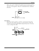
The operation of the Analyzer/Controller can be verified by replacing the input from a
cell with a precision check resistor across the Analyzer/Controller input terminals. In
addition, an 8550 ohm resistor (Honeywell Part No. 31233300) can be wired in place of
the inputs from the temperature compensator to simulate 25º C, the reference
temperature. The unit will display a simulated “process value” appropriate for the check
resistor installed. (Equations showing the relationship between resistor rating and
displayed value are provided below.) If the displayed value is incorrect, the
Analyzer/Controller should be serviced.
This technique can be used two ways:
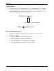
• Offline - Install the precision check resistor temporarily in place of the input from
either cell to check the operation of the Analyzer/Controller. When correct operation
has been verified, remove the resistor and replace the field wiring.
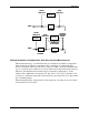
• Online - To provide a constant check of the Analyzer/Controller’s operation in a
critical process, connect the conductivity cell to the Cell 1 input terminals; instead of
a Cell 2 input, install a check resistor at the Cell 2 input terminals. The Cell 2
“process value” should always be the appropriate value for the resistor (see equations
below). Configure an alarm to monitor this value.
Set cal factor and calibration trim for ideal conditions
When a check resistor is used instead of cell input, the Analyzer/Controller must be set
for theoretically ideal conditions to achieve display of the appropriate value for the
installed resistor. This means that you set the cell calibration factor to 1.00 and remove
the calibration trim for the cell input being replaced by the check resistor.
Calculations for conductivity, resistivity, and TDS
To verify instrument operation at any point of measurement, calculate the check
resistance needed to simulate that value. (It is assumed that you have selected a display
measurement value that is within the range of your cell constant; see 2.1for ranges.) The
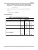
equation used depends on the measurement type. For concentration check values see the
table on the following page.
Conductivity check resistance (ohms) = Cell Constant (cm
-1
) x 10
6
Conductivity (microSiemens/cm)
Resistivity check resistance (ohms) = Cell Constant (cm
-1
) x Resistivity (ohm-cm)
TDS check resistance (ohms) = Cell Constant (cm
-1
) x 10
6
TDS (ppm)/TDS factor
(TDS factor has units of ppm/microSiemens-cm
-1
)