
user manual


Index
236 UDA2182 Universal Dual Analyzer Product Manual January 2009
divert the discharge to drain.
3 Relay 2 activates solenoid valve S2 for the preset buffer time (1 to 1999 seconds) to direct buffer
solution past the electrodes by gravity.
4 After a stable reading is reached or the set maximum buffer time elapses, the 9782 stores the new
calibration value using automatic buffer recognition. Diagnostics detect excessive instability or
offset, prevent erroneous calibrating and can activate an alarm, depending on configuration. If the
diagnostic fails, an error message is always displayed on the alarm stripe (see Section 12).
If an unacceptable value is obtained, it will be rejected and the previous value will be retained for
uninterrupted operation.
5 All valves are deactivated to resume measurement of the sample.
6 A delay period (1 to 1999 seconds) can be configured to permit the measurement to stabilize on the
process sample. At the end of the delay period normal alarm, control and output operation
resumes. The “HOLD” and “AUTOSEQUENCE” messages are cleared.
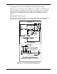
S4
S2
buffer
solution
process
sample
pH
electrode
to process
to drain
9782
Items outside this area
provided by user
rinse water
S 1
Figure 15-12 Rinse and One-Point Calibration
Rinse and two-point calibration sequence
With this function, rinse and one-point standardization operations are performed as
described previously according to the configured schedule. If two-point calibration is to
be performed periodically, then after the configured number of standardization
operations, Steps 4a and 4b shown below are also performed (before Step 5 above) to
make the slope adjustment.
4a Relay 3 activates solenoid valve S3 for the configured buffer time to direct the second buffer flow to
the electrodes.
4b After stability is reached or the set maximum buffer time elapses, the instrument calculates and
stores a new slope value using automatic buffer recognition. Diagnostics detect excessive
instability or offset, prevent erroneous calibrating and can activate an alarm, depending on
configuration. If the diagnostic fails, an error message is always displayed on the alarm stripe (see
Section 9).
If an unacceptable value is obtained, it will be rejected and the previous value will be retained for
uninterrupted operation.