
user manual


January 2009 UDA2182 Universal Dual Analyzer Product Manual 243
Slope adjustments..................................................138
Slope Overrange....................................................191
Slope Underrange ..................................................191
Software version number .......................................107
Solu Temp Coeff ................................................63, 65
Solu Temp Comp .........................................63, 64, 69
Solution Temp Too High ........................................190
Solution Temp Too Low .........................................190
Solution Unstable...................................................191
Solution Unstable...................................................190
Source......................................................................73
SP High Limit ...........................................................93
SP Low Limit ............................................................93
SP Source....................................................81, 82, 85
Specific and Cation Conductivity Setup....................38
Specifications.............................................................5
Sqr Root...................................................................85
Square Root.............................................................85
Standard and solution temperature compensation.....3
Standard pH Buffer Values for Automatic Buffer
Recognition ........................................................139
standardization.......................................................138
Starting/Stopping the Auto Cycle .............................31
Status Displays ........................................................41
Status Messages......................................................24
Switch.......................................................................89
Switch selections......................................................88
Symbol Definitions ....................................................iv
System Status Messages.......................................189
T
Tag Name ................................................................24
Tag Names ............................................................109
TDS conversion factor....................................154, 155
TDS Factor...............................................................68
TEMP n OVERRANGE ..........................................189
TEMP n UNDERRANGE........................................189
Temp Type.............................................62, 64, 68, 71
Temp Units.................................................63, 64, 109
Temperature Compensation.......................................6
Temperature Input Calibration................................183
Terminal Designations for Conductivity..................128
Terminal Designations for Dissolved Oxygen.........129
Terminal Designations for Durafet II Electrode.......119
Terminal Designations for Durafet II Electrode with
Cap Adapter.......................................................126
Terminal Designations for Durafet II Electrode with
External Preamplifier..........................................125
Terminal Designations for Durafet III Electrode......118
Terminal Designations for Durafet III Electrode with
Cap Adapter.......................................................127
Terminal Designations for HPW7000 System 122, 123
Terminal Designations for Meredian Electrode with
External Preamplifier..........................................124
Terminal Designations for Meredian II Electrode ...120
Terminal Designations for Option Board ................133
Terminal Designations for ORP..............................121
Terminal Designations for Power, Analog Output, and
Relay Output ......................................................132
Time proportional output ..............................42, 75, 76
Time Proportional Output Relay...............................76
Tune Set 2 ...............................................................97
Two Input Display.....................................................25
Two-cell Applications..............................................209
U
Unit Reset ..............................................................108
Unpacking..................................................................9
Unpacking and Preparing.........................................10
Upper range limit defaults ........................................66
User interface.............................................................1
V
Variables..................................................................43
Voltage outputs ......................................................176
W, X, Y, Z
Wall Mounting Dimensions.......................................14
Watertight corrosion-resistant case............................4
Web pages...............................................................49
Weight........................................................................7
Wire Len Feet...........................................................69
Wire Len Meters.......................................................69
Wire Length............................................................108
wire size .................................................................108
Wire Size AWG ........................................................69
Wire Size Sq mm .....................................................70
Wireless Interface ......................................................6
Wiring for immunity compliance ...............................16
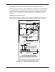
Wiring terminals and board location .......................116