
user manual

Power Wiring
18 UDA2182 Universal Dual Analyzer Product Manual January 2009
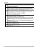
Step Action
screws that hold the retainer and slide the retainer to the left until the retainer tabs
disengage from the terminal boards.
4
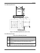
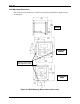
Refer to Figure 7-1 for the location of the Power Supply/Analog Output/Relay Output board.
Insert a screwdriver into the hole in the middle of the terminal board and pull out gently.
Slide the board half way out. There is a notch in the terminal board into which you can slide
the retainer tabs and hold the board in place while wiring.
5
Install a fused disconnect switch in the power line that will be connected to the Analyzer.
•If a 230/240 Vac line is to be connected, use a 0.15 amp fuse.
•If a 110/120 Vac line is to be connected, use a 0.30 amp fuse.
Fuse must be a Time-Delay or Slo-Blo type.
6
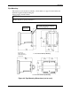
Each unit has (4) 22.22mm [.87"] dia. holes on the bottom of the unit for lead wires and
conduit fittings. Conduit fittings to be supplied by the user.
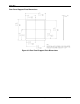
Feed the power wiring through the wiring port on the bottom of the case. Connect the power
wiring to terminals L1 and L2/N as shown in Figure 4-1. Connect the Green safety ground
wire to the grounding stud on the case.
Attention: Terminal 1 must be connected to the ground stud on the grounding bar using
a #14 AWG UL/CSA-approved wire.
7
Slide the retainer to the left then slide the terminal board back into place. Slide retainer to
engage the tabs and tighten the screws.
8
Close the Bezel and secure four captive screws to a torque value of .20 Nm (1.5 Lb-in).
Power up the unit.
Do not apply power until the bezel is closed.