
user manual

Configuration
62 UDA2182 Universal Dual Analyzer Product Manual January 2009
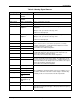
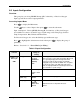
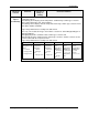
AC 2 Cal 2 Auto Cycle 2
Calibration Point 2
Auto Cycle 2 digital output (Cycle Start Source) configuration selection
See Table 6-16 Auto Cycling Configuration.
AC 2 Fail Auto Cycle 2 Failure Auto Cycle 2 Failure is active whenever an Auto Cycle 2 failure occurs
Auto Cycle 2 digital output (Cycle Start Source) configuration selection
See Table 6-16 Auto Cycling Configuration.
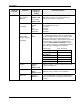
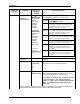
Input 1 Cal Input 1 Calibration This signal goes TRUE when the calibration factor for input 1 is being
calculated. The TRUE state is active for less than one second.
Input 2 Cal Input 2 Calibration This signal goes TRUE when the calibration factor for input 2 is being
calculated. The TRUE state is active for less than one second.
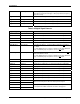
Output 1 Cal Output 1 Calibration The signal indicates when the Output 1 calibration values are being
changed. The signal goes TRUE when the “4ma Offset” or “20ma
Offset” is being modified. The signal goes FALSE when the value is
entered.
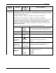
Output 2 Cal Output 2 Calibration The signal indicates when the Output 2 calibration values are being
changed. The signal goes TRUE when the “4ma Offset” or “20ma
Offset” is being modified. The signal goes FALSE when the value is
entered.
Output 3 Cal Output 3 Calibration The signal indicates when the Output 3 calibration values are being
changed. The signal goes TRUE when the “4ma Offset” or “20ma
Offset” is being modified. The signal goes FALSE when the value is
entered.
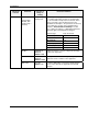
DgtlVar 1 Digital Variable 1 Initial values of Digital Variable 1 applied at power on.
DgtlVar 2 Digital Variable 2 Initial values of Digital Variable 2 applied at power on.
DgtlVar 3 Digital Variable 3 Initial values of Digital Variable 3 applied at power on.
DgtlVar 4 Digital Variable 4 Initial values of Digital Variable 4 applied at power on.