
Product manual


Installation
12 UDC2500 Universal Digital Controller Product Manual 4/07
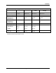
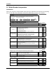
2.3 Model Number Interpretation
Introduction
Write your controller’s model number in the spaces provided below and circle the corresponding
items in each table. This information will also be useful when you wire your controller.
Instructions
Select the desired key number. The arrow to the right marks the selection available.
Make the desired selections from Tables I through VI using the column below the
proper arrow. A dot ( ) denotes availability.
Key Number
- - - - _ _ _ _
_
-
_
KEY NUMBER - UDC2500 Single Loop Controlle
r
Selection
Digital Controller for use with 90 to 264Vac Power DC2500
Digital Controller for use with 24Vac/dc Power DC2501
TABLE I - Specify Control Output and/or Alarms
TABLE II - Communications and Software Selections
0 _ _ _
1 _ _ _
2 _ _ _
10
Base-T
Ethernet
(Modbus RTU)
Plus Auxiliary
Output/Digital
Inputs 3 _ _ _
_ 0 _ _
_ A _ _
_ B _ _
_ L _ _
aa
No Selection
_ _ 0 _
_ _ _ 0
_ _ _ R
0 _
C _
E _
None (Can be used as an indicator only)
Current Output (4 to 20ma, 0 to 20 ma)
Software Selections
One Alarm Relay Only
Standard Functions, Single Display
Dual Display with Auto/Manual
Set Point Programming (12 Segments) Dual Display, Auto/Manual
Limit Controller
Communications
None
Infrared interface
Auxiliary Output/Digital Inputs (1 Aux and 1 DI or 2 DI)
RS-485 Modbus Plus Auxiliary Output/Digital Inputs
None
Reserved
Output #1
_ A
_ T
Output #2 and Alarm
#1 or Alarms 1 and 2
A _
T _
R _
_ E
Open Collector Plus Alarm 1 (5 Amp Form C Relay)
_ B
Availability
Infrared Interface Included (Can be used with a Pocket PC)
_ 0
E-M Relay (5 Amp Form C) Plus Alarm 1 (5 Amp Form C Relay)
Solid State Relay (1 Amp) Plus Alarm 1 (5 Amp Form C Relay)
Electro Mechanical Relay (5 Amp Form C)
Solid State Relay (1 Amp)
No Additional Outputs or Alarms
Description
_
_
V
_ _ _ __ _ _ _ _
_
_
_
I
_ _ _
IIIII IV VI
Open Collector transistor output
Dual 2 Amp Relays (Both are Form A) (Heat/Cool Applications)
DC 2500 2501
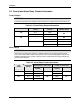
TABLE III - Input 1 can be changed in the field using external resistors
Selection
1 _ _
2 _ _
3 _ _
_ 00
_ 10
bb
TABLE IV - Options
0 _ _ _ _
1 _ _ _ _
cc
2 _ _ _ _
_ 0 _ _ _
_ T _ _ _
_ _ 0 _ _
_ _ _ 0 _
_ _ _ _ 0
Approvals
CE, UL and CSA (Standard)
Stainless Steel Customer ID Tag - 3 lines w/22 characters/line
None
CE, UL, CSA and FM
Tags
Future Options
None
TC, RTD, mV, 0-5V, 1-5V, 0-20mA, 4-20mA, 0-10V
Input 2
Input 1
None
None
None
TC, RTD, mV, 0-5V, 1-5V, 0-20mA, 4-20mA
0-5V, 1-5V, 0-20mA, 4-20mA
CE Only
Availability
TC, RTD, mV, 0-5V, 1-5V