UltraKey Lite Keyboard controller for VideoBloX and MAXPRO-Net Matrix Systems HJC5000 Installation and User Guide Document 800-07422 – Rev A – 08/10
Installation and User Guide
Revisions Issue Date Revisions 800-03854 rev A 02/2009 New document. 800-03854 rev B 03/2009 Updated the MaxPRO map code. 800-03854 rev C 04/2009 Corrected the controller login PIN code; corrected IP address p.
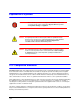
Explanation of Symbols WARNING! The exclamation point in a red octagon is a WARNING. Failure to take or avoid a specific action could result in physical harm to a person or irreparable damage to equipment.
Changes or modifications not expressly approved by the party responsible for compliance could void the user’s authority to operate the equipment. Users of the product are responsible for checking and complying with all federal, state and local laws and statutes concerning the monitoring and recording of video and audio signals. Honeywell Systems Group shall not be held responsible for the use of this product in violation of current laws and statutes.
Consider using a UPS source to ensure satisfactory performance. Using replacement parts or accessories other than the original manufacturers may invalidate the warranty. CAUTION RISK OF ELECTRIC SHOCK DO NOT OPEN CAUTION: TO REDUCE THE RISK OF ELECTRIC SHOCK, DO NOT REMOVE COVER (OR BACK). NO USER-SERVICEABLE PARTS INSIDE. REFER SERVICING TO QUALIFIED SERVICE PERSONNEL. Important Safety Instructions BEFORE OPERATING OR INSTALLING THE UNIT, READ AND FOLLOW ALL INSTRUCTIONS.
10. REPLACEMENT PARTS - When replacement parts are required, be sure the service technician has used replacement parts specified by the manufacturer or have the same characteristics as the original part. Unauthorized substitutions may result in fire, electric shock or other hazards.
UltraKey Lite Controller Installation and User Guide Contents 1 About this Document and the UltraKey Lite . . . . . . . . . . . . . . . . . . . . . . . . . . . . . 15 Document Overview . . . . . . . . . . . . . . . Finding More Information. . . . . . . . . . . . . Typographical Conventions . . . . . . . . . . . UltraKey Lite Specifications . . . . . . . . . . . Shipping Checklist . . . . . . . . . . . . . . . . UltraKey Lite Port Connections and Descriptions 2 . . . . . . . . . . . . . . . . . . . .
UltraKey Lite Controller Installation and User Guide Figures Figure 1-1 UltraKey Lite Port Connections . . . . . . . . . . . . . . . . . . . . . . . . . . . . . . . . 19 Figure 1-2 Terminal Box Front and Back Ports . . . . . . . . . . . . . . . . . . . . . . . . . . . . . . 20 Figure 2-1 UltraKey Lite Controller Keyboard Layout . . . . . . . . . . . . . . . . . . . . . . . . . . . 22 Figure 2-2 The UltraKey Navigation Controls Figure 3-1 LCD and LCD Navigation Keys . . . . . . . . . . . . . . . .
Figure 5-2 Change Password Page . . . . . . . . . . . . . . . . . . . . . . . . . . . . . . . . . . . . 69 Figure 5-3 System Configuration LCD Menu Tree - All Modes . . . . . . . . . . . . . . . . . . . . . .
UltraKey Lite Controller Installation and User Guide Tables Table 1-1 UltraKey Lite Specifications. . . . . . . . . . . . . . . . . . . . . . . . . . . . . . . . . . . 17 Table 1-2 Shipping Checklist . . . . . . . . . . . . . . . . . . . . . . . . . . . . . . . . . . . . . . . 18 Table 2-1 LCD Menu Navigation During Set Up . . . . . . . . . . . . . . . . . . . . . . . . . . . . . 23 Table 2-2 VideoBloX Key Functions . . . . . . . . . . . . . . . . . . . . . . . . . . . . . . . . . . . .
1 About this Document and the UltraKey Lite In this section: • • • • • • Document Overview, page 15 Finding More Information, page 16 Typographical Conventions, page 16 UltraKey Lite Specifications, page 17 Shipping Checklist, page 18 UltraKey Lite Port Connections and Descriptions, page 19 The UltraKey Lite (HJC5000) is a replacement for the Honeywell HEGSBLX controller and is compatible with Honeywell VideoBloX and MAXPRO-Net Video Matrix Systems.
About this Document and the UltraKey Lite Finding More Information Refer to the online literature library to access other electronic documents in PDF format including data sheets, quick references, installation and user guides, specifications, software and product notices: http://www.honeywellvideo.com. Also see the back cover for international web sites and contact details.
UltraKey Lite Controller Installation and User Guide UltraKey Lite Specifications Table 1-1 UltraKey Lite Specifications Parameter Value Power Requirements 10.8 to 13.2 VDC @ 1 Ampere (A) or POE (48 VDC, Class 3) Connector Types 1×Ethernet (10Base-T, 100Base-TX) RJ45 with LED 1×RS232/422/485 RJ45 with LED LCD Type: STN, Positive Image Backlight: Blue-White Characters: 122×32 Dots USB Type: A Version: USB1.
About this Document and the UltraKey Lite Shipping Checklist The following is included with your UltraKey Lite Controller shipment. Use of accessories is dependent on the type of installation. Ultrakey Lite can be connected to the matrix system either by serial port or Ethernet RJ45 connections. Table 1-2 Shipping Checklist Quantity Part Use with... 1 Ultrakey Lite keyboard controller All installations. 1 Ultrakey Lite installation and user guide All installations.
UltraKey Lite Controller Installation and User Guide UltraKey Lite Port Connections and Descriptions Figure 1-1 UltraKey Lite Port Connections Power RJ45 Ethernet RS232 and RS422/485 Serial port USB 8 1 8 1 Pins numbered from right to left DC Power Port Supports 12V (±10%) DC/1 A power input. Use the power adapter included with the shipment and insert one of the four adapters based on your local power requirements.
About this Document and the UltraKey Lite RS232, RS422/485 Serial Port Note These ports are used to connect to MAXPRO-Net RS232 or RS422 and to VideoBloX NetCPU, Standard CPU and Lite CPU RS422. An isolated surge protection is suggested when using RS485/RS422 and when cabling between buildings. Note For MAXPRO net installations, COM1 (RS422) and COM2 (RS485) are configured using the controller LCD menu and cannot be used at the same time. Note Serial port 1 can be either RS485 or RS422.
2 Using the UltraKey Lite Controller You may need to learn how to use the UltraKey Lite both before and after you begin configuring. In this section: • • • • Logging Onto the Controller, page 21 Using the UltraKey Lite to Navigate the LCD Menus, page 22 VideoBloX Key Functions, page 24 MAXPRO Key Functions, page 27 Note Key availability is dependent on the mode selected.
Using the UltraKey Lite Controller Using the UltraKey Lite to Navigate the LCD Menus There are a variety of ways to navigate both the LCD menus during configuration and set up as well as during normal operation with your matrix system. Figure 2-1 shows all of the keys and other elements of the UltraKey Lite controller. See Table 2-2 for UltraKey Lite key functions when used with a VideoBloX system. See Table 2-3 for UltraKey Lite key functions when used with a MAXPRO-Net system.
UltraKey Lite Controller Installation and User Guide Figure 2-2 The UltraKey Navigation Controls Forward key (or up) Touch Pad and Ring Touch pad ring Right arrow key Left arrow key Touch pad - Use like a laptop mouse pad Backward or reverse key (or down) LCD Keys LCD Left arrow key Right arrow key Up arrow key Down arrow key Joystick Move the joystick left and right or up and down to navigate the menus Table 2-1 LCD Menu Navigation During Set Up Task Options To confirm a change or enter t
Using the UltraKey Lite Controller Table 2-1 LCD Menu Navigation During Set Up (cont’d) Task Options To move back through the menus one level at a time • KEYS: Press Alt > Clr To scroll through the top level menu options • • • • LCD KEYS: Press the right/left arrow keys TOUCH PAD: Rotate your finger clockwise or counter-clockwise TOUCH PAD RING: Press the right / left arrows JOYSTICK: Move right/left To scroll through the secondary level menu options You can use any of these ways to access the L
UltraKey Lite Controller Installation and User Guide Table 2-2 VideoBloX Key Functions (cont’d) ID Key Description Function in Camera Mode PCK (Cam Mode) PCK (Device Mode) 7 Pause Play Rev Selects previous camera Prev Stop 8 Review Puts keyboard in Device mode NA Pause 9 Record Store a preset (preshot) Store Rec 10 Search Puts keyboard in Device mode NA Index - 11 Pause Play Fwd Selects next camera Next Play 12 Tour Tour 1 Runs SEQ 250 on CPU Tour 2 Runs SEQ 251 on CPU Tour
Using the UltraKey Lite Controller Table 2-2 VideoBloX Key Functions (cont’d) ID Key Description Function in Camera Mode PCK (Cam Mode) PCK (Device Mode) 28 Mon A Depends on controller address. EG, Add 1 SEQ201 run, Add 2, SEQ202 run, and so on.
UltraKey Lite Controller Installation and User Guide MAXPRO Key Functions Note Use Figure 2-1 to locate each key as labeled in the ID column.
Using the UltraKey Lite Controller Table 2-3 28 MAXPRO Key Functions (cont’d) ID Key Description Key Code Default MAX Function UltraKey 18 Clear 808 Pause 808 19 Monitor 61 Monitor Monitor 20 Camera 73 Camera Camera 21 Alt 10 Alt Group 4 22 PTZ Call 94 Light PTZ Call 23 Touch wheel right 105 (1-8) None Shuttle R 23 Touch wheel left 106 (1-8) None Shuttle L 23 Touch ring Up 65 Up Arrow Up Arrow 23 Touch ring Down 69 Down Arrow Down Arrow 23 Touch ring Le
UltraKey Lite Controller Installation and User Guide Table 2-3 MAXPRO Key Functions (cont’d) ID Key Description Key Code Default MAX Function UltraKey 21+30 F10+F5 18 Pause Group 6 21+30 F10+F6 53 None Print Select 21+30 F10+F7 101 Scroll Down Scroll Down 21+30 F10+F8 54 F6 Freeze 21+30 F10+F9 28 Scan Halt Group 10 24/26 Focus + 89 Focus Near Focus + 24/26 Focus - 88 Focus Far Focus - Document 800-07422 Rev A 08/10 29
Using the UltraKey Lite Controller 30
3 Installing UltraKey Lite with VideoBloX In this section: • • • • Navigating the LCD Configuration Menus, page 31 Installing and Configuring a Serial Connection, page 32 Installing and Configuring an Ethernet Connection, page 36 (Optional) Configuring UltraKey Lite Using the Web Browser, page 41 Note For all installations, refer to the applicable VideoBloX or VideoBloX Lite installation or user guides for more information.
Installing UltraKey Lite with VideoBloX Figure 3-1 LCD and LCD Navigation Keys Numeric keypad and Ent key Left arrow key Down arrow key Up arrow key Right arrow key Figure 3-2 VideoBloX LCD Configuration Menu Tree Mode Selection: VideoBloX Connection Serial Port Configuration Ethernet IP Address 159.099.251.
UltraKey Lite Controller Installation and User Guide Table 3-1 Serial Port COM1 and COM2 Pin Assignments Serial Port Type Pin Signal COM1 RS422 1 RX + 2 RX – 5 GND 7 TX – 8 TX + 7 T/R – 8 T/R + RS485 Note For a list of accessories see Shipping Checklist on page 18 and for port connections see UltraKey Lite Port Connections and Descriptions on page 19. 1. Select the applicable adapter plug and insert it into the AC adapter. Push to click it into place. See Figure 3-3. 2.
Installing UltraKey Lite with VideoBloX Figure 3-4 RJ45 to DB9 Male Adapter for VideoBloX and VideoBloX Lite CPUs Controller RJ45 to DB9 male adapter VideoBloX Serial Port RJ45 network cable Figure 3-5 Direct RJ45 Serial Port Connection for VideoBloX NetCPUs Controller VideoBloX Serial Port RJ45 network cable Figure 3-6 VB master: 1--RS422_TX – 2--RS422_TX + 3--RS422_RX + 4--RS422_RX – 5--GND VideoBloX Serial Port RS422 Connection Example VideoBloX Serial Port (RS422) VIdeoBlox Master Connection
UltraKey Lite Controller Installation and User Guide 1. If not already done, install and connect the controller to a power source. 2. From the home screen, press Alt > Clr to enter the System Configuration: System Set menu. 3. Enter the PIN password 3434. The System Set: Mode screen displays. 4. Press the LCD right arrow key to enter the Mode Selection menu. 5. Scroll to and select VideoBloX. Press Ent. Step 3: Configure Address, Baud Rate or IP for VideoBloX Mode 1. Press Alt > Clr.
Installing UltraKey Lite with VideoBloX Note In this field, you are setting the VideoBloX NetCPU IP address. To set the UltraKey Lite IP address or enter the main configuration menus, press Alt > Clr and see Step 3: Set and Configure for an Ethernet Connection on page 38. 16. Use the numeric keypad to enter an IP address as required, then press Ent. IP Address 159.099.251.230 Step 4: Configure VideoBloX Mode Default Settings While Powering Up 1.
UltraKey Lite Controller Installation and User Guide Table 3-2 RJ45 Ethernet Pin Assignments Port Pin Signal RJ45 Ethernet 1 TX + 2 TX – 3 RX+ 6 RX – 1. Select the applicable adapter plug and insert it into the AC adapter. Push to click it into place. See Figure 3-3. 2. Plug the AC adapter into the controller power port and the adapter into a power source. 3. Plug an RJ45 network cable from the network to the controller Ethernet port. Up to 32 controllers can be connected to the network.
Installing UltraKey Lite with VideoBloX Step 3: Set and Configure for an Ethernet Connection 1. Press Alt > Clr. If prompted, enter the password 3434 to enter the System Set top menu. 2. Press the LCD down arrow to scroll to the System Set: Config menu. 3. Press the right arrow key to enter the Configuration menus. 4. Press the LCD up/down arrow keys to scroll through the options (restore default, VB settings, maxpro settings, network, language, back light, slider update, hardware test, about). 5.
UltraKey Lite Controller Installation and User Guide 5. Press the LCD up/down arrow keys to scroll through the options (serial port, network, language, back light, slider update, cascade linkage, hardware test, about). 6. Scroll to the Configuration: Network menu, then press Ent. 7. There are three sub-menus in this menu (Show Net Infor, DHCP, and Manual Settings).
Installing UltraKey Lite with VideoBloX 2. When you are at the Network: Manual Setting menu, press Ent, then press the LCD up/down arrow keys to set the UltraKeyLite network parameters (IP address, gateway, netmask and DNS). 3. Press the LCD up/down arrow keys to scroll through the menu options to select IP Address, then press Ent to select. Network: a. Using the numeric key pad, enter an IP address, then press Ent to save. The LCD menu displays the message: IPAddr Changed.
UltraKey Lite Controller Installation and User Guide Step 5: Setting the Keyboard Address While Powering Up While powering up, when the Time Left 3 menu displays, press certain keys (see Table 3-3) to set the keyboard address.
Installing UltraKey Lite with VideoBloX Figure 3-8 UltraKey Lite Login Page Step 1: Configure UltraKey Lite to VideoBloX Mode 1. Log into the web browser. 2. From the top menu, click the Configuration tab. See Figure 3-9. 3. From the side menu, click the System Configurations tab. 4. From the System Mode drop down list, select VideoBlox. 5. From the System Language drop down list, select English or French. 6. From the Background Light drop down list select ON or OFF. 7.
UltraKey Lite Controller Installation and User Guide Note By default, addresses 1– 5 in the VideoBloX NetCPU are set for serial connection. Please change this in the NetCPU configuration if you want to use addresses 1– 5 for Ethernet connection. 3. Under VB Device Network Setting, enter the IP address and Port Number of the VideoBloX system. 4. Click Apply to save the configuration, Cancel to exit without saving, or Default to restore all factory default values. 5.
Installing UltraKey Lite with VideoBloX 2. Under Serial Port1 Settings, select the following from each drop-down list as required: • • • • • 3. Baud Rate: 1200, 9600, 19200 or 57600 bps. The default for VideoBloX is 19200. Parity: none Stop Bits: 1 bit Data Bits: 8 bits Serial Mode: RS422 Click Apply to save the configuration, Cancel to exit without saving, or Default to restore all factory default values.
UltraKey Lite Controller Installation and User Guide Step 4: Configuring the Dynamic Keys You can configure the hard keys on the web server. 1. From the side menu, click DynKey Configuration. Figure 3-13 DynKey Configuration Tab 2. In the drop-down menu, select the key you want to configure. 3. In the right column, select the function you want to add to the hard key, then click Add. That selected function appears in the center column. 4.
Installing UltraKey Lite with VideoBloX 46
4 Installing UltraKey Lite with MAXPRO-Net In this section: • • • • Navigating the LCD Configuration Menus, page 47 Installing and Configuring a Serial Connection, page 49 Installing and Configuring an Ethernet Connection, page 56 (Optional) Configuring UltraKey Lite Using the Web Browser, page 60 Note For all installations, refer to the applicable MAXPRO-Net installation or user guides for more information.
Installing UltraKey Lite with MAXPRO-Net Figure 4-1 LCD and Navigation Keys Numeric keypad and Ent key Left arrow key Down arrow key Up arrow key Figure 4-2 Right arrow key MAXPRO LCD Menu Tree Mode Selection: MAXPRO Connection By Serial Port RS232 directly Configuration By Ethernet Maxpro offline keyboard 1 RS422 indirectly Maxpro Key Code Fixed Camera Camera 1 Maxpro Setting Keyboard ID Baud Rate Joystick Speed Server IP Serial Port Serial Port Mode 1 to 32 9600 / 19200 bps Nor
UltraKey Lite Controller Installation and User Guide Installing and Configuring a Serial Connection Step 1: Connect to the UltraKey Lite Serial Port Note For a list of accessories see Shipping Checklist on page 18 and for port connections see UltraKey Lite Port Connections and Descriptions on page 19. Note COM1 (RS422) and COM2 (RS485) are configured using the controller LCD menu and cannot be used at the same time. See Table 4-1 below.
Installing UltraKey Lite with MAXPRO-Net Figure 4-3 RS232 Serial Port Connection MAXPRO Serial Port (RS232) 4 RJ45 to DB9 female 4 RJ45 define: 1--RS485_2+/RS422_2_TX+/ RS422_1_RX+ 2--RS485_2-/RS422_2_TX-/ RS422_1_RX3—NC 4--RS232RX 5--RS232GND 6--RS232TX 7--RS485_1-/RS422_1_TX8--RS485_1+/RS422_1_TX+ *RS485_2/RS422_2_TX and RS232 use same UART_AC 1 RJ45 to DB9 female 4 RJ45 to DB9 female RJ45 (Ultrakey Lite) #4(RX) #5(GND) #6(TX) DB9(M axpro) #3(TX) #5(GND) #2(RX) 1 RJ45 Network Cable 3 P
UltraKey Lite Controller Installation and User Guide Figure 4-5 RS232 Serial Port Connection and MX18 MAXPRO Serial Port (RS232) and MX18 RJ45 define: 1--RS485_2+/RS422_2_TX+/ RS422_1_RX+ 2--RS485_2-/RS422_2_TX-/ RS422_1_RX3—NC 4--RS232RX 5--RS232GND 6--RS232TX 7--RS485_1-/RS422_1_TX8--RS485_1+/RS422_1_TX+ *RS485_2/RS422_2_TX and RS232 use same UART_AC MX18 7 7 RJ11 Flat Ribbon Cable straight 3 PSU 3 PSU Controller 1 RJ11 Flat Ribbon Cable straight Controller 8 RS232 Connections with an RJ45 to D
Installing UltraKey Lite with MAXPRO-Net RS422 Connections Using a Converter and the Terminal Box 1. Select the applicable adapter plug and insert it into the AC adapter. Push to click it into place. See Figure 4-6. 2. Connect an RJ45 network cable from the RJ45 port on the terminal box to the controller serial port. 3. Connect an RS422 cable from the RS422 terminal plug pins on the terminal box to an RS422 to RS232 converter (supplied by the installer or customer). 4.
UltraKey Lite Controller Installation and User Guide Figure 4-9 RS232 Serial Port Connection and Terminal Box RS422 MAXPRO Serial Port (RS232) and Terminal Box (RS422) RS232 RS232 RS232 to RS422 PL1 1--RS485_1+/RS422_1_TX+ 2--RS485_1-/RS422_1_TX3--RS485_2+/RS422_2_TX+ /RS422_1_RX+ 4--RS485_2-/RS422_2_TX/RS422_1_RX5--RS232RX 6--RS232TX 7--RS232GND 8--RS232GND *RS485_2/RS422_2_TX and RS232 use same UART_AC RS232 to RS422 RS422 RS422 DB9 male PL1 PL2 2 DB9 male PL1 Terminal Box PL2 2 RJ45 RJ45 1
Installing UltraKey Lite with MAXPRO-Net Step 2: Configure the Controller for MAXPRO Mode Note The controller factory defaults to VideoBloX mode, Address 1, baud rate 19200 bps. 1. If not already done, install and connect the controller to a power source. The UltraKey Lite LCD displays. 2. From the home screen, press Alt > Clr to enter the System Configuration: System Set menu. 3. Enter the PIN password 3434. The System Set: Mode screen displays. 4.
UltraKey Lite Controller Installation and User Guide Note If the controller cannot connect to the MAXPRO network, then this step cannot be completed until the connection is established. However, the MAXPRO settings menu can be configured even if the controller has not connected to the MAXPRO network; that is, the LCD displays that MAXPRO is offline. 5. Use the LCD up/down arrow keys to select RS232 or RS422, then press Ent. 6.
Installing UltraKey Lite with MAXPRO-Net Baud Rate: 19.2 KB Data Bit: 7 Parity: Even Stop Bit: 1 Installing and Configuring an Ethernet Connection Step 1: Connect to the UltraKey Lite Ethernet Port Table 4-3 RJ45 Ethernet Pin Assignments Port Pin Signal RJ45 Ethernet 1 TX + 2 TX – 3 RX+ 6 RX – 1. Plug an RJ45 network cable from the network to the controller Ethernet port. Up to 99 controllers can be connected to the network. See Figure 4-11. 2. Connect MAXPRO-Net to the network.
UltraKey Lite Controller Installation and User Guide Step 2: Configure the Controller for MAXPRO Mode Note The controller factory defaults to VideoBloX mode, Address 1, baud rate 19200 bps. Follow the same steps as with the serial connection, Step 2: Configure the Controller for MAXPRO Mode on page 54. Step 3: Set and Configure for an Ethernet Connection 1. From the MAXPRO connection submenu, select Ethernet.
Installing UltraKey Lite with MAXPRO-Net Step 4: Configure the Controller for an Ethernet Connection 1. Press Alt > Clr to exit from the VideoBloX configuration menu. 2. Press Alt > Clr a second time to enter the System Set top menu. 3. Press the LCD down arrow key to scroll to the System Set: Config menu. 4. Press the right arrow key to enter the Configuration menus. 5.
UltraKey Lite Controller Installation and User Guide When the nework configures successfully, the user can enter the Show Net Infor menu to see the IP Address, IP Address, DNS, Gateway and Netmask. Network: Manual Setting Manually Configuring the Network Manually configuring the network using the Manual Setting menu: 1. Press the LCD down arrow key to scroll to the Network: Manual Setting menu 2.
Installing UltraKey Lite with MAXPRO-Net Step 5: Setting the Keyboard Address While Powering Up While powering up, when the Time Left 3 menu displays, press certain keys (see Table 4-4) to set the keyboard address.
UltraKey Lite Controller Installation and User Guide Figure 4-12 UltraKey Lite Login page Step 1: Configure UltraKey Lite to MAXPRO Mode 1. Log into the web browser. 2. From the top menu, click the Configuration tab. See Figure 4-13. 3. From the side menu, click the System Configurations tab. 4. From the System Mode drop-down list, select MAXPRO. 5. From the System Language drop-down list, select English or French. 6. From the Background Light drop-down list select ON or OFF. 7.
Installing UltraKey Lite with MAXPRO-Net 3. Enter the IP address and Port Number of the MAXPRO-Net server under MAXPRO Device Network Setting. 4. Under Serial Port Setting, select a Baud Rate from the drop-down list. Options are 9600 or 19200 bps. 5. Select a Connect Mode from the drop-down list. Options are 232 or 422. 6. From the Joystick speed drop-down list, select Normal or High. 7.
UltraKey Lite Controller Installation and User Guide 4. Click Apply to save the configuration, Cancel to exit without saving or Default to restore all factory default values. Figure 4-15 Serial Port Configuration Tab Step 3B: Configure the Controller for an Ethernet Connection 1. From the side menu, click IP Configuration. 2. In each of the fields, enter IP address, subnet mask, gateway and DNS values. 3.
Installing UltraKey Lite with MAXPRO-Net Figure 4-17 64 DynKey Configuration Tab 2. In the drop-down menu, select the key you want to configure. 3. In the right column, select the function you want to add to the hard key, then click Add. That selected function appears in the center column. 4. Repeat step 3 to add another function to the selected key. 5. Click Apply to save. Note No more than 10 functions can be configured to a hard key.
5 System Administration and Troubleshooting In this section: • • System Administration Using the Controller LCD, page 65 System Administration Using the Web Browser, page 68 System Administration Using the Controller LCD To navigate all configuration LCD menus, see Figure 5-3 on page 70. Logging in and Navigating to the System Set: Config Menu 1. If not already done, install and connect the controller to a power source. The UltraKey Lite LCD displays. 2.
System Administration and Troubleshooting Adjusting the Back Light 1. Log into the controller. 2. From the System Set: Config menu, press the LCD up/down arrow keys to scroll to Back Light. Press Ent. 3. Use the LCD up and down arrow keys or the rotate the touch pad to adjust the back light intensity. Configuration Back Light Updating the Touch Pad Firmware Slider firmware should be updated whenever a new slider firmware version is released.
UltraKey Lite Controller Installation and User Guide Testing the Hardware 1. Log into the controller. Configuration 2. From the System Set: Config menu, press the LCD up/down arrow keys to scroll to Hardware Test. Press Ent. Hardware test 3. Press the LCD up/down arrow keys and press Ent to select one or all of the following test options: • • • • 4. Key: When you press a key, the key value and its state is displayed on LCD.
System Administration and Troubleshooting Table 5-1 HJC5000 UltraKey Lite Controller Default Settings (cont’d) Settings Protocol VideoBlox Mode Address 1 Baud Rate 19200 bps Control Mode Serial Port IP Address 192.168.1.11 Default Back Light Off System Administration Using the Web Browser Logging into the Web Browser 1. If not already done, navigate to, or copy and paste, the applicable IP address into your web browser: • • LAN connections: for example, http://192.168.1.
UltraKey Lite Controller Installation and User Guide When the process is complete, the message Upgrade success displays and the system reboots. WARNING! Figure 5-1 Do not power off the keyboard during upgrading. Serious damage can occur to the firmware, rendering the keyboard inoperable. Software Upgrade Warning Message Rebooting UltraKey Lite 1. Log into the web browser. 2. From the top menu, click the System Reboot tab. The Reboot System window opens. 3.
System Administration and Troubleshooting Figure 5-3 System Configuration LCD Menu Tree - All Modes Keyboard ID Maxpro Settings Serial Port Mode Address Server Port VB Settings Baud Rate Server IP Control Mode Joystick Speed IP Address Restore Defaults Baud Rate About Key Serial Port Hardware Test Configuration System Set: Configuration Slider Joystick Slider Update Back Light Adjust Bg Light Up/Down Slide Language English/French Show Net Infor Network Manual Setting DHCP 70
Honeywell Systems Group (Head Office) 2700 Blankenbaker Pkwy, Suite 150 Louisville, KY 40299, USA www.honeywellvideo.com +1.800.796.2288 Honeywell Systems Group Northern Europe Ampèrestraat 41 1446 TR Purmerend, The Netherlands www.honeywell.com/security/nl +31.299.410.200 Honeywell Systems Group Europe/South Africa Aston Fields Road, Whitehouse Industrial Estate Runcorn, Cheshire, WA7 3DL, UK www.honeywell.com/security/uk +44.01928.