UMC800 Controller Installation and User Guide Sensing and Control Doc. No.
Notices and Trademarks Copyright 2001 by Honeywell Release F April, 2001 Warranty/Remedy Honeywell warrants goods of its manufacture as being free of defective materials and faulty workmanship. Contact your local sales office for warranty information. If warranted goods are returned to Honeywell during the period of coverage, Honeywell will repair or replace without charge those items it finds defective.
About This Document Abstract This document provides descriptions and procedures for the installation, operation and maintenance of the UMC800 Controller hardware. References The following list identifies all documents that may be sources of reference for material discussed in this publication.
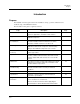
Symbol Definitions The following table lists those symbols that may be used in this document to denote certain conditions. Symbol Definition This DANGER symbol indicates an imminently hazardous situation, which, if not avoided, will result in death or serious injury. This WARNING symbol indicates a potentially hazardous situation, which, if not avoided, could result in death or serious injury. This CAUTION symbol may be present on Control Product instrumentation and literature.
Contents Introduction ............................................................................................. 1 Purpose ........................................................................................................................ 1 UMC800 Controller ...................................................................................................... 2 CE Conformity (Europe) ............................................................................................... 2 UMC800 Overview ..
Maintenance ......................................................................................... 63 Overview .................................................................................................................... 63 Routine Maintenance ................................................................................................. 64 Controller Calibration ................................................................................................. 65 Replacement Procedures...........
Tables Table 1 Controller plug-in I/O module types................................................................................................................6 Table 2 Communication port descriptions ..................................................................................................................10 Table 3 Operating limits .............................................................................................................................................
Figures Figure 1 UMC800 components.....................................................................................................................................3 Figure 2 UMC800 controller hardware.........................................................................................................................5 Figure 3 551 operator interface.....................................................................................................................................
Introduction Purpose Introduction Purpose This Installation and User guide assists in the installation, start up, operation, maintenance and troubleshooting of the UMC800 Controller.
Introduction UMC800 Controller UMC800 Controller The UMC800 is industrial process control equipment that must be mounted. The wiring terminals must be enclosed within a panel. CE Conformity (Europe) This product is in conformity with the protection requirements of the following European Council Directives: 73/23/EEC, the Low Voltage Directive, and 89/336/EEC, the EMC Directive. Conformity of this product with any other “CE Mark” Directive(s) shall not be assumed.
UMC800 Overview UMC800 Description UMC800 Overview UMC800 Description The Universal Multiloop Controller (UMC800) is a modular controller designed to address the analog and digital control requirements of small unit processes.
UMC800 Overview Feature Summary through the Configuration port allows remote access to the controller via the Control Builder and User Utility programs. This will enable trouble shooting, configuration changes and firmware upgrade. The optional communications board adds two bi-directional, multi-drop RS 485 serial communication interfaces to the controller CPU module. The COMM A port uses Modbus RTU protocol and is a master/slave link allowing up to 31 controllers to be connected to a single host computer.
Equipment Identification Controller Components Equipment Identification Controller Components Enclosure The UMC800 controller illustrated in Figure 2 consists of a single metal enclosure that houses the following controller components: • Power supply module that plugs into the controller common backplane. • CPU module with two serial communications ports. An optional communications board provides two RS485 serial communication ports (slave and master) that support Modbus® RTU protocol.
Equipment Identification Controller Components I/O modules Eleven different module types can be installed in the controller to support both analog and digital inputs and outputs of various types and signal levels. The signal type and I/O capacity for each module type is indicated in Table 1. Table 1 Controller plug-in I/O module types Module Type Signal Types Maximum I/O I/O per card Maximum no.
Equipment Identification Operator Interface Operator Interface The UMC800 operator interface (Figure 3, Figure 4, and Figure 5) provides a graphic LCD display and a monoplaner keyboard to allow operator access to all controller functions. The operator interface becomes operational once a valid database is configured in the controller. Modification and customization of the operator interface is performed using Control Builder software.
Equipment Identification Control Builder Control Builder All controller and operator interface configuration is performed using Control Builder software on a separate PC operating with WindowsTM 95 or WindowsTM NT 4.0. All configuration is performed off-line (computer disconnected from the controller and operator interface). The configuration is downloaded in a separate operation as a complete file through a dedicated RS-232 communication port on the controller.
Equipment Identification Control Builder Completed configurations may also be saved on 3.5" floppy disk and loaded into the controller and operator interface through an optional 3.5" floppy disk drive, eliminating the need for a direct connection of a PC to the controller. Each analog signal flow line of the configuration may be labeled with an 8-character name, 4-character engineering unit definition, and may have a decimal point location specified.
Equipment Identification Serial Communication Ports Serial Communication Ports The controller contains dedicated serial ports for external communications. These are described in Table 2. Table 2 Communication port descriptions Communication Port (on CPU Module) 10 Description Configuration Configuration Port - This RS232 port is a dedicated connection for communications with a PC running the Control Builder configuration program. The communications link layer protocol is proprietary.
Pre-Installation Considerations Introduction Pre-Installation Considerations Introduction Installation of the controller consists of mounting and wiring the controller according to the guidelines given in this section. The controller is industrial control equipment that must be panel mounted within an enclosure. The wiring terminals must be enclosed within the enclosure.
Pre-Installation Considerations Introduction Electrical considerations The controller is considered “open equipment” per EN 61010-1, Safety Requirements for Electrical Equipment for Measurement, Control, and Laboratory Use, Part 1: General Requirements. Conformity with 72/23/EEC, the Low Voltage Directive requires the user to provide adequate protection against a shock hazard. The user shall install this controller in an enclosure that limits OPERATOR access to the rear terminals.
Pre-Installation Considerations Introduction Permissible wire bundling Table 4 shows which wire functions should be bundled together. Table 4 Permissible wiring bundles Bundle No. 1 Wire Functions • Line power wiring • Earth ground wiring • Control relay output wiring • Line voltage alarm wiring 2 Analog signal wire, such as: • Input signal wire (thermocouple, 4 mA to 20 mA, etc.
Pre-Installation Considerations Introduction 14 UMC800 Controller Installation and User Guide Release F 4/01
Mounting and Wiring Site Preparation Mounting and Wiring Site Preparation The UMC800 must be mounted within an enclosure. Hardware is provided to surface mount the controller to a panel or other suitable surface. Be sure that there is sufficient clearance for mounting the controller enclosure and the external wiring. UMC enclosure and components The controller enclosure houses all circuit assemblies of the UMC controller. See Figure 7.
Mounting and Wiring Mounting the Controller Power requirements The standard supply uses 100/240 Vac or Vdc input ranges for its source. The input requirements are listed in Table 5. Instructions for wiring the power supply are found in Table 5.
Mounting and Wiring Mounting the Controller Enclosure mounting dimensions 13.027 330.89 11.77 298.96 inches Dimensions = _________ millimeters 11.37 286.26 0.25 6.35 7.0 3.013 177.8 76.53 NOTE: Allow 7.0” (178 mm) depth to mounting dimensions for controller enclosure and cabling. To mount the controller so that the power supply is at the top, rotate the mounting dimensions 90 degrees.
Mounting and Wiring Plug-in Module Locations Plug-in Module Locations Common backplane The controller backplane provides common connections for the power supply, CPU and I/O modules. All modules are installed into the backplane in their assigned slots designated by the controller model number. [See Controller model number (page 21).] The power supply and CPU occupy the slots on the right side of the enclosure. See Figure 9.
Mounting and Wiring Plug-in Module Locations I/O Module PWA Terminal Block + OUT4 ! _ + OUT3 _ + OUT2 0-20mA _ + OUT1 _ Figure 10 I/O module PWA and terminal Table 6 I/O module identification ID Number Terminal Block Color Part Number Analog Input (AI) 1 Black 46190305-503 Analog Output (AO) 2 Black 46190314-503 Digital Input (DI) - Logic 3 Black 46190311-503 Digital Input (DI) - DC 4 Black 46190347-501 Digital Input (DI) - AC 5 Red 46190350-501 Digital Input (DI) - 16 point
Mounting and Wiring Plug-in Module Locations I/O module limits The controller backplane accommodates I/O module types, subject to the limitations as shown in Table 7. Slot Locations identify the allowable locations in the controller for each I/O module type. Maximum Allowed describes the maximum I/O configuration for each I/O type in a controller.
Mounting and Wiring Plug-in Module Locations Controller model number The controller model number specified on your purchase order indicates the I/O module types and the assigned slot location of each I/O module present in the controller. The number fields that identify I/O modules are defined below. Example of controller model number Controller Model Number 8001 - 000 - 0E - 01122300 - 56800000 I/O module types and controller locations for . . .
Mounting and Wiring Plug-in Module Locations Verify I/O module locations The table below outlines the steps for identifying and recording the I/O module types in the controller. Step Action 1 Verify that the module types installed in the controller card slots are correct according to the controller model number. Refer to Table 6 to identify the module types. 2 Use to record the location, module type and signal type/range for each I/O module installed in the controller.
Mounting and Wiring Signal Wiring Signal Wiring I/O module wiring Terminal blocks are installed to the front of the I/O modules for connecting field device wiring as shown in Figure 11. Terminal blocks are color coded and numbered to identify the I/O module type. (See Table 6.) The terminal blocks are removable so that I/O modules can be replaced without disconnecting the field wiring from the terminal blocks. Wire gauge sizes 16 to 22 AWG can be used to connect to the terminal blocks.
Mounting and Wiring Signal Wiring Analog input / analog output field wiring Shielded twisted pairs are recommended (and required for CE approval) for analog input (AI) and analog output (AO) module field wiring. If a cabinet shield termination point is not available, the optional shield termination bracket may be used, (specify part number 51309814-501). The shield termination point is a bracket attached at the top and/or bottom on the front of the controller enclosure.
Mounting and Wiring Signal Wiring Analog inputs (module ID 1) A universal Analog Input module accepts a variety of input signals from field devices as summarized in Table 9. Figure 13 illustrates the terminal block connections for the various inputs. See Specifications section for more details on all I/O module specifications. One AI module can be configured to accept multiple input types.
Mounting and Wiring Signal Wiring Field wiring for one pH sensor input (module ID C) Figure 14 indicates the recommended wiring for one pH sensor input. Note that two analog input channels are required, one for the pH sensor and one for temperature. Similar wiring may be used for additional sensors. A UMC800 controller can accommodate 2 power modules for a total of up to 8 pH inputs.
Mounting and Wiring Signal Wiring Analog outputs (module ID 2) The Analog Output (AO) module provides four outputs at 0 mA to 20 mA (configurable for 4 mA to 20 mA or any span between 0 mA to 20 mA). When not used for an analog output, an output channel may be used to power a transmitter with 24 Vdc power. The controller will support up to 4 AO modules, for a total of 16 outputs. Figure 15 shows the terminal connections for the AO module.
Mounting and Wiring Signal Wiring Digital inputs Three types of Digital Input (DI) modules accept four types of input signals. 1. Logic Input (Module ID 3 and B) 2. DC Input (Module ID 4) 3. AC Input (Module ID 5) 4. Pulse/Frequency Input (Module ID D) Each type is described on the following pages. Figure 16 shows the terminal block connections for all DI modules. See Specifications section for details on all I/O module specifications.
Mounting and Wiring Signal Wiring Module B Identifiable by 32 screws 2 + Each odd-numbered terminal is internally grounded.
Mounting and Wiring Signal Wiring Digital outputs There are four types of Digital Output (DO) modules that provide three types of Off/On control. 1. Relay (alarm) output (Module ID 6) 46190308-503 2. DC output (Module ID 7) 46190341-501 3. AC output (Module ID 8) 46190344-501 4. AC high output (Module ID A) 46190344-502 Figure 17 shows the terminal block connections for the DC output and AC output DO modules. See Specifications section for details on all I/O module specifications.
Mounting and Wiring Signal Wiring The Digital Output module with relay outputs (Module ID 6) contain jumpers to set the de-energized state of the relay contacts. The relays are factory set to normally open (NO) for each output on the relay alarm module, as shown in Figure 18. To change the state of the contacts: Use a pair of needle-nose pliers and move the jumper from the location NO (normally closed) to the location NC (normally closed).
Mounting and Wiring Signal Wiring Pulse input/frequency input module with digital outputs Figure 19 shows the terminal block connections for Pulse/Frequency Input Module. See Specifications section for details on all I/O module specifications. ATTENTION 16 Point Digital Input module (ID D) has 32 terminals. If you are using 2 wires per DI, use 22 gage wires so all 32 wires can fit through the rubber grommet in the controller case. See Figure 19.
Mounting and Wiring Signal Wiring Pulse input/frequency input jumpers The Pulse/Frequency Input Module with Digital Outputs (Module ID D) contain jumpers to set the deenergized Input Filter Cutoff Frequency. All four inputs are factory set to 500 KHz as shown in Figure 23. To change, use needle nose pliers and move the jumper(s) to the desired position. See the figure below for the default positions and jumper settings for 100 KHz and 5 KHz.
Mounting and Wiring Signal Wiring V supply Choose a supply that is compatible with the environmental requirements of your application. The supply voltage must be within the requirement of both the transmitter and the pulse input card. Typically a low cost 12 Vdc unregulated supply can be used in most applications provided in meets applicable regulatory requirements. 1k ohm termination resistors (RT) are built into the pulse frequency card.
Mounting and Wiring Signal Wiring Pulse frequency card outputs The pulse frequency card outputs are open collector drivers designed to drive a maximum of 100 mA. All Pulse Frequency card digital outputs are optically isolated from each other. The maximum supply voltage must not exceed 27 Volts dc.
Mounting and Wiring Wiring Communication Links Wiring Communication Links Serial communications ports The controller communicates through a number of serial ports. The CPU module contains two serial ports. One is an RS 232 connection to a PC and another is dedicated for connection to the operator interface. The CPU with optional communications features two additional RS 485 serial ports. The serial port connectors on the CPU module are shown in Figure 23.
Mounting and Wiring Wiring Communication Links Table 10 Summary of communication link connections to controller Communication Link to . . . Link Type From Controller Port Connect Cable PC or laptop (via Null Modem cable or via modem) RS 232 CONFIGURATION Up to 50 ft cable lengths (Supplied by user) (9-pin “D” connector) To Port Serial port of PC. Reference Data Null Modem cable, 9-pin Male/Female See Table 11.
Mounting and Wiring Wiring Communication Links CONFIGURATION cable Table 12 Null modem cable construction PC Connector 9-Pin “D” Female Pin 38 UMC800 9-Pin “D” Male Pin 2 2 3 3 5 5 4 4 6 6 7 7 8 8 UMC800 Controller Installation and User Guide Order part number 51404755-501 Release F 4/01
Mounting and Wiring Wiring Communication Links Installing ferrite clamp for CE compliance This procedure ensures that unwanted radio frequency noise is filtered. It is required for CE compliance. Parts needed Part # Quantity Description 047260 1 Ferrite cable clamps 089037 2 Nylon cable ties Installing ferrite clamp Step Action Disconnect all power to the instrument. 2 See Figure 24.
Mounting and Wiring Wiring Communication Links DISPLAY connector (to operator interface) The controller is connected to the operator interface through a 15-pin D-Type connector cable. One cable end is connected to the DISPLAY connector of the controller. The other end connects to a 10-pin in-line connector at the rear of the operator interface case. This cable end must be made, since some installations may require the cable to be run through conduit.
Mounting and Wiring Wiring Communication Links Connector location at the rear of the operator interface 551 Operator Interface Rear Connector for Cable from Controller Connector Terminal Wiring Signal Name Wire Color Terminal Number RXRX+ RX Shd. TX Shd. TXTX+ Sig. Gnd Sig. Gnd Outer Shd.
Mounting and Wiring Wiring Communication Links COMM A and B connectors (optional) The CPU module equipped with the optional communication board provides two additional RS 485 communications ports with Modbus RTU protocol support. COMM A port allows the UMC800 controller to network with up to 31 other slave UMC800 controllers and devices on a Modbus link. COMM B port allows the UMC800 controller to be a master to up to 16 slave UMC800 controllers and devices on a Modbus link.
Mounting and Wiring Wiring Communication Links RS 485 serial communications When connecting the controller to a RS 485 communication link (see Figure 27), you must use termination resistors at each end of the link. The following cables with the listed resistor values can be used for connecting the controller. RS 485 Cables: Belden #9271 (or equivalent) with 120 ohm termination resistors (2,000 ft. maximum) Belden #9182 (or equivalent) with 150 ohm termination resistors (4,000 ft.
Mounting and Wiring Remote Access Remote Access Overview Remote controller access via dial-up modem is available via the communication setup. An external modem is required at the controller and is connected to the standard RS232 configuration port (marked “CONFIGURATION”). All functions of the Control Builder and User Utility programs can be performed over this link. Remote access functions include on-line monitoring, configuration upload and download, and firmware upgrade.
Mounting and Wiring Remote Access Modem configuration Before connecting a modem to the controller’s RS232 port (marked “CONFIGURATION”), the modem must be configured with the following settings: • Baud Rate = 9600 • Parity = None • 1 stop bit • 8 data bits • No handshaking • Ignore DTR • Suppress result codes • Suppress echo • Auto answer • Disable command recognition (only necessary if the modem has this capability) Some of these settings may be settable via switches.
Mounting and Wiring Remote Access Modem configuration examples Below are procedures for setting up the following commercially available modems: • 3Com US Robotics 56K Data/Fax External Modem • Zoom 56K Dualmode External Modem • Best Data 56SX Data Fax External Modem • SixNet VT-MODEM Industrial External Modem 3Com US Robotics 56K Data/Fax External Modem Step 1 Action Ensure that the switches are set to the factory settings: Switch Setting Position Function 1 OFF UP Normal DTR operations 2
Mounting and Wiring Remote Access Step 9 Release F 4/01 Action Set the modem switches to the following: Switch Setting Position Function 1 ON DOWN Modem ignores DTR (Override) 2 OFF UP Verbal (word) results 3 OFF UP Suppresses result codes 4 ON DOWN Suppresses echo 5 OFF UP Modem answers on first ring 6 ON DOWN CD always ON (Override) 7 OFF UP Loads Y0-Y4 configuration from user-defined nonvolatile memory (NVRAM) 8 OFF UP Disables command recognition (dumb mode) 10 C
Mounting and Wiring Remote Access Zoom 56K Dualmode External Modem Step Action 1 Connect the modem to a PC. If your PC’s RS232 port has a 25-pin connector, use a DB-25 male to DB-25 female RS232 cable. If your PC’s RS232 port has a 9-pin connector, use a DB-25 male to DB-9 female modem cable. 2 Connect power to the modem. 3 Power up the modem. 4 Run a serial communication port program such as Hyperterminal. 5 Within the communication program, select the port to which the modem is connected.
Mounting and Wiring Remote Access Best Data 56SX Data Fax External Modem Step Action 1 Connect the modem to a PC. If your PC’s RS232 port has a 2- pin connector, use a DB-9 male to DB-25 female modem cable. If your PC’s RS232 port has a 9-pin connector, use a DB-9 male to DB-9 female RS232 cable. 2 Connect power to the modem. 3 Power-up the modem. 4 Run a serial communication port program such as Hyperterminal. 5 Within the communication program, select the port to which the modem is connected.
Mounting and Wiring Remote Access SixNet VT-MODEM Industrial External Modem Step Action 1 Connect the modem to a PC. If your PC’s RS232 port has a 25 pin connector, use a DB-9 male to DB-25 female modem cable. If your PC’s RS232 port has a 9 pin connector, use a DB-9 male to DB-9 female RS232 cable. 2 Connect power to the modem. You will need to supply an external power supply with a DC voltage between 10 and 30 VDC. 3 Power-up the modem.
Mounting and Wiring Power Supply Wiring Power Supply Wiring The power wiring is connected to the power terminals of the power supply in accordance with accepted wiring practices and is summarized in Table 14 shows the terminal connections for the power wiring. F 3,15 AT 250V L1 L2 / N Figure 28 Power supply terminal connections CAUTION Do not apply power to the controller at this time.
Operation Power Up / Power Down Operation Power Up / Power Down Power-up A sequence of checks are performed by the controller anytime power is applied to the controller. These checks are a set of internal diagnostics that are completed in less than 10 seconds after power up and verify the integrity of the controller hardware, the configuration database and firmware. Communication between the operator interface and controller is established automatically after these checks are completed.
Operation Operational Modes and Controls Operational Modes and Controls There are three operational modes defined in the UMC800 to provide safe operating environments for users to implement changes and perform tasks on the controller and operator interface. 1. PROGRAM Mode 2. RUN Mode 3. OFFLINE Mode Safeguards are built into the operating system to prevent conditions that could otherwise cause process upsets or equipment malfunctions.
Operation Operational Modes and Controls 2. From the Operator Interface. Mode changes can be made from SET MODE display or the Calibrate AI and AO displays of the operator interface with certain restrictions. When the manual switch is set to PROGRAM, you cannot change the mode to RUN or OFFLINE using the operator interface. The operator interface is active in all modes. 3. Through the CONFIGURATION Port.
Operation Operational Modes and Controls Table 15 Controller mode switch summary Controller Mode Manual Switch setting RUN Mode Control through the Configuration Port or Operator Interface Unrestricted mode changes. The mode selected via the Configuration port or operator interface overrides the controller manual mode switch position. OFFLINE PROGRAM Can override OFFLINE mode to set controller to PROGRAM mode. No mode changes can be made.
Operation File Downloading File Downloading Downloading configuration files, recipes and other files to the controller can be accomplished two ways: 1. Download from a PC or other device connected the Configuration port (serial port) of the controller. 2. Using the operator interface to download files stored on a floppy disk. These files include recipes, setpoint profiles and data storage files. There are mode restrictions on the downloading of certain configuration files.
Operation Code Download Download via CONFIGURATION port A downloading tool in the control builder software can be used to download configuration files to the controller. The downloading tool first verifies that a valid configuration file exists for the controller. Next, a dialog box asks if you want to set the controller to Program mode in preparation for downloading.
Operation Warm Start / Cold Start Warm Start / Cold Start Housekeeping and diagnostic routines are performed during power up sequence of the controller and prior to the controller microprocessor starting normal scan processing. During this sequence all logic outputs are OFF and all analog outputs are held to their zero output states. After this activity, the controller may perform either a cold start or a warm start of the controller configuration. Warm start is the default mode of start-up.
Operation Status Indicators Number of analog input cards Time to complete one full scan (in milliseconds) 8 1700 9 1900 10 2100 11 2300 12 2500 13 2700 14 2900 15 3100 16 3300 Status Indicators Status LEDs Four LEDs on the CPU module (shown in Figure 30) indicate the operating status of the controller and are described in Table 18. Table 18 Controller status LEDs Designation POWER State Steady on Blinking Indication Power is applied to the controller backplane. Diagnostic indication.
Operation Status Indicators OFFLINE RUN CONFIGURATION PROGRAM Controller Status Indicators POWER Lo BA T FORCE BA T DISPLAY CPU Module Re pl ac e ba ttery w ith Tadi ran TL5 10 1/ S on ly. Us e of an other ba tte ry ma y pre se nt a r is k of fi re o r expl osi on . See use rs g ui de for i nstr uct io ns. RUN _ 100 - 24 0 V ~ 50 / 6 0 Hz 100 VA MAX. Figure 30 Controller status LEDs Controller Status The status of various controller parameters can be viewed through a number of displays. 1.
Operation RS 485 Port Configuration (Communication Board Option) RS 485 Port Configuration (Communication Board Option) COMM A and B ports UMC controllers equipped with the optional communications board feature two RS 485 serial communications ports (COMM A and COMM B) on the CPU module. See Figure 31 for location of the port connectors. See Wiring Communications links, Page(36) for more details on the port wiring. The controller firmware supports Modbus RTU protocol for the ports.
Operation RS 485 Port Configuration (Communication Board Option) 62 UMC800 Controller Installation and User Guide Release F 4/01
Maintenance Overview Maintenance Overview This section covers procedures in the maintenance, calibration and replacement of the controller and its components. Maintenance to the controller consists of the following procedures: • Routine maintenance • Calibration of I/O modules. (The backplane is factory calibrated only.) • Field replacement of controller components Warranty • Warranty repair is by board replacement.
Maintenance Routine Maintenance Routine Maintenance Controller maintenance Normal routine maintenance of the controller is not necessary other than a periodic physical inspection of the controller enclosure and wiring for any signs of deterioration or dust and dirt. Battery replacement Replace the battery located on the CPU when the LoBATT LED lights or the low battery diagnostic is indicated.
Maintenance Controller Calibration Controller Calibration ATTENTION All Analog Input (AI) and Analog Output (AO) modules are factory calibrated to 0.1% accuracy. If this accuracy is sufficient for your applications, there is not need to recalibrate the modules. If greater accuracy is required, the field calibration procedures will provide a 0.05% accuracy.
Maintenance Controller Calibration Factory calibration Factory calibration of controller components is performed before shipment to 0.1% accuracy. Calibration values are contained in a number of the controller components, namely: the CPU, Backplane, and AI and AO modules. Figure 32 shows the various components in which calibration data is stored. • Calibration functions and parameters for the user interface are stored in memory on the CPU.
Maintenance Controller Calibration Field calibration Field calibration of controller components is limited to AI modules and AO modules. Individual channels of the modules can be calibrated at 0% and 100% of their range. Individual channels can be calibrated at a single point within the range through zero offset (bias) adjustment.
Maintenance Controller Calibration T/C, mV, V - Ground Terminal 4 to 20 mA Source + * 10 11 + - 9 RTD 7 + 6 - 5 RTD 4 RTD + 3 - 2 Ground Terminal RTD 1 Ground Terminal RTD Input (3 wires) + mV or V Source RTD - * A 250 ohm resistor is required for the input range.
Maintenance Controller Calibration Wire Jumper ST1 ST1 + OU T 4 ! _ + OU T 3 _ + OU T 2 Analog Output Module 0-20mA _ + OU T 1 _ Figure 34 AO module jumper ST1 Release F 4/01 UMC800 Controller Installation and User Guide 69
Maintenance Replacement Procedures Replacement Procedures The following tables outline the procedures for replacement of the controller components. Field replacement is limited to the Printed Wiring Assembly (PWA) level. Use Figure 35 to locate controller components for replacement.
Maintenance Replacement Procedures CAUTION TO PRESERVE THE CONTROLLER CONFIGURATION PRIOR TO PERFORMING ANY REPLACEMENT PROCEDURES OR REMOVING POWER TO THE CONTROLLER: • Be certain that the LoBatt LED is OFF. (MEMORY – LOW BATTERY diagnostic is not active.) • Force a cold start of the controller by setting the manual mode switch on the controller to PROGRAM and then to RUN and allow the controller to complete its start up sequence.
Maintenance Replacement Procedures Replacing the power supply fuse The power supply input circuit is protected with a fuse. Use the steps in the table below to replace the fuse on the power supply module. Step Action 1 Remove power from the controller. 2 Locate the fuse holder located on the power supply module. See Figure 36. 3 Using a slotted screwdriver, remove the fuseholder cap by rotating it counterclockwise. 4 Replace the fuse with the proper size and type.
Maintenance Replacement Procedures Replacing the battery A lithium battery is used as a keep alive voltage for the volatile memory (RAM) that contains the controller configuration. The battery is installed in a compartment on the CPU module. Follow the steps in the table below to replace the CPU battery. CAUTION The battery used in this device may present a risk of fire or chemical burn if mistreated. Do not recharge, disassemble, heat above 212 °F (100 °C), or incinerate.
Maintenance Replacement Procedures Replacing I/O modules If any I/O modules need to be replaced, follow the steps in the table below. Step Action 1 Remove power from controller. 2 Remove front cover by loosening the two screws at the top of the enclosure. 3 Locate the I/O module you want to replace. See figure. Remove terminal board from front of module by pressing the two locks at top and bottom of the terminal block and pulling the block straight out. See Figure 37.
Maintenance Replacement Procedures Locks 12 11 10 2 I/O Module Identification 9 8 7 Field Wiring Terminals 6 5 4 3 2 1 Locks Figure 37 I/O module terminal blocks (not shown: 16 point DI) Replacing the CPU module Follow the steps in the table below for replacement of the CPU module in the controller. Please note that field calibration values for AI modules and CJC references are stored on the CPU. These values must be restored, if necessary, after a CPU is replaced.
Maintenance Replacement Procedures Replacing the power supply module Step Action 1 Remove power from controller. 2 Disconnect power wiring from power supply terminals. 3 Remove front cover by loosening the two screws at the top of the enclosure. 4 Remove five screws on the front of power supply securing the CPU module and power supply. 5 Unplug CPU module from controller slot by pulling it straight out from its slot.
Maintenance Replacement Procedures Replacing the backplane Step Action 1 Remove power from controller. 2 Disconnect power wiring from power supply terminals. 3 Remove front cover by loosening the two screws at the top of the enclosure. 4 Remove five screws on the front of power supply securing the CPU module and power supply. 5 Unplug CPU module from controller slot by pulling it straight out from its slot. 6 Unplug power supply module from enclosure by pulling it straight out from its slot.
Maintenance Replacement Procedures Step 18 Action Reconnect power wiring to proper terminals on power supply as shown. F 3,15 AT 250V Hot Neutral L1 L2 / N Ground 78 19 Replace front cover and secure with two screws. 20 Restore power to controller. 21 Verify configuration. Perform calibration of AI modules and CJC references (if using T/C) for all channels if greater than 0.1 % accuracy is required.
Diagnostics and Troubleshooting Overview Diagnostics and Troubleshooting Overview This section provides diagnostic and troubleshooting information to help in evaluating controller operating status, diagnosing fault conditions and taking actions to correct faults. An overview of diagnostic routines and detail of the indicators used to inform users of controller operating status is provided.
Diagnostics and Troubleshooting Controller Diagnostics Controller status LEDs Status indicators on the controller consist of four LEDs that indicate good and fault conditions in the controller. These LEDs indicate controller status and help to aid troubleshooting when the operator interface is not nearby or when the controller is not communicating with the operator interface or PC. Table 19 describes the LEDs and the possible states with their meaning.
Diagnostics and Troubleshooting Fault Detection and Troubleclearing Fault Detection and Troubleclearing Interpreting the controller status and determining if any corrective action is necessary can be done by referring to Table 20 and Table 21. Actions to clear fault conditions usually consist of restarting the controller, and if the fault reoccurs, replacing the suspected faulty component.
Diagnostics and Troubleshooting Fault Detection and Troubleclearing Controller Diagnostic Summary (In the User Utility and Operator Interface) Menu Item SYSTEM Controller LED on CPU Status TASK FAULT RUN LED off. Fault Detection / Troubleclearing Possible Cause Controller Action Software failure. Function blocks are not executed. And POWER LED flashes 3 times. User Action 1. Force a cold start. (Toggle controller mode switch from PGM to RUN.) 2. Upgrade controller software. 3.
Diagnostics and Troubleshooting Fault Detection and Troubleclearing Controller Diagnostic Summary (In the User Utility and Operator Interface) Menu Item CPU Controller LED on CPU Status ADDRESS ERROR POWER LED flashes 4 times. Fault Detection / Troubleclearing Possible Cause Controller Action User Action Address Error Detected. Executes normally. 1. Force a cold start. (Toggle controller mode switch from PGM to RUN.) 2. Isolate system from noise and force a cold start. 3. Replace CPU board.
Diagnostics and Troubleshooting Fault Detection and Troubleclearing Controller Diagnostic Summary (In the User Utility and Operator Interface) Menu Item CPU Controller LED on CPU Status SPURIOUS INTERRUPT POWER LED flashes 4 times. Fault Detection / Troubleclearing Possible Cause Controller Action User Action Spurious Interrupt. Executes normally. 1. Force a cold start. (Toggle controller mode switch from PGM to RUN.) 2. Isolate system from noise and force a cold start. 3. Replace CPU board.
Diagnostics and Troubleshooting Fault Detection and Troubleclearing Controller Diagnostic Summary (In the User Utility and Operator Interface) Menu Item RTC Controller LED on CPU Status BATTERY FAILURE POWER LED flashes 8 times Fault Detection / Troubleclearing Possible Cause Controller Action RTC battery failed on power-up Time and date is set to 00:00:00, January 1, 1970. User Action 1. If Lo BAT LED is off, cycle power. 2. If Lo BAT LED is on, replace battery and cycle power.
Diagnostics and Troubleshooting Fault Detection and Troubleclearing Controller Diagnostic Summary (In the User Utility and Operator Interface) Menu Item Controller LED on CPU Status Fault Detection / Troubleclearing Possible Cause Controller Action User Action COMM A GOOD − − − none COMM A BOARD FAILURE POWER LED flashes 13 times. The COMM A port hardware has a serious failure. Executes normally. Replace Comm board.
Diagnostics and Troubleshooting Fault Detection and Troubleclearing Fault detection and troubleclearing Table 21 describes the status messages that appear on the I/O Module Diagnostics displays in the user utility and operator interface, as well as the status indications of the POWER LED located on the controller CPU module.
Diagnostics and Troubleshooting Fault Detection and Troubleclearing I/O Module Diagnostics (In The User Utility and Operator Interface) Menu Item MODULE 1 through MODULE 16 Controller LED on CPU Status BAD MODULE Fault Detection / Troubleclearing Possible Cause POWER LED flashes 11 times. Analog input or analog output board does not have factory coefficients, or the I/O board is not a supported type. Controller Action 1. If the error is an User Action Replace module.
Diagnostics and Troubleshooting Fault Detection and Troubleclearing Modem troubleshooting Controller modem problems will typically show one of two symptoms. • The modem does not answer, or • the modem answers but does not establish communications. Table 22 Controller modem troubleshooting Modem does not answer Cause Solution Modem not powered. Apply power. Modem not configured for auto answer. Check modem configuration and correct. Modem not properly connected to phone line.
Diagnostics and Troubleshooting Fault Detection and Troubleclearing 90 UMC800 Controller Installation and User Guide Release F 4/01
Parts List UMC800 Controller Parts List UMC800 Controller If you require replacement or spare parts for the UMC controller, you can order them by referring to the table below and contacting your Honeywell representative. Replacement parts Part Description Analog Input Card Part Number 46190305-503 Analog Output Card 46190314-503 DO Relay Output Card 46190308-503 DO AC Output 46190344-501 DO AC Output (2 @ 2 A and 4 @ 0.
Parts List UMC800 Controller Part Description Part Number I/O Red Terminal Block 46190204-501 Controller Fuse for 100-240 V supply (1 each) Controller Fuse for 24 V supply (1 each) 46182886-002 Grommet Kit (Power Terminal Cover, Grommets (16) 51404796-501 Shield Termination* 51309814-501 Ferrite Suppressor* 51404883-501 250 Ohm Shunt Resistor Kit (for mA ranges) (4) 46181080-503 Null Modem 9-pin “D” connector** (Cable for connecting Controller to PC) 51404755-501 Cable for connecting Con
Specifications Introduction The following tables contain electrical, physical, safety and performance specifications for the UMC800 controller. Controller Design Parameter Controller Description CPU with two serial communication ports,* power supply, and backplane assembly. Capable of supporting up to 16 input /output modules. *CPU option provides additional RS 485 communications with Modbus RTU protocol.
Specifications I/O Module Configuration Component Parameter Accuracy (at reference conditions) Description Factory configured accuracy = ± 0.1 % of range Cold junction accuracy = ± 0.5 °C Field calibration accuracy = ± 0.
Specifications I/O Module Configuration Component Logic Inputs Parameter Description Inputs per Module 6 (ID 3) or 16 (ID B) dry contact Switching Voltage 5 Vdc Switching Current 5 mA (Module ID 3 and B) AC Outputs (Module ID 8) Digital Outputs Release F 4/01 DC Outputs (Module ID 7) Outputs per Module 6 6 (current sinking) Operating Voltage 15 Vac to 240 Vac 10.2 Vdc to 26.
Specifications I/O Module Configuration Component Pulse/Frequency Inputs with Digital Outputs Parameter Input 1 to 4 Voltage Levels Description Logic Input High Vih: Logic Input Low Vil: Absolute Max: Absolute Min: 3.0 Vdc 1.0 Vdc 27 Vdc 0.
Specifications Design Design Parameter Scan Rate Description 1 AI module – (1 to 4 analog inputs): 333 milliseconds 2 AI modules – (5 to 8 analog inputs): 500 milliseconds 3 AI modules – (9 to 12 analog inputs): 700 milliseconds 4 AI modules – (13 to 16 analog inputs): 900 milliseconds 5 AI modules – (17 to 20 analog inputs): 1100 milliseconds 6 AI modules – (21 to 24 analog inputs): 1300 milliseconds 7 AI modules – (25 to 28 analog inputs): 1500 milliseconds 8 AI modules – (29 to 32 analog inputs): 1700
Specifications Design Parameter System Interconnections Description Operator Interface (DISPLAY) Maximum Distance Between Controller File and Operator Interface: 50 feet Cable Type: 15 conductor, shielded Cable termination: 15-pin “D” connector at the controller end; removable screw type terminal strip at operator interface end. Operator Interface power (24 Vdc) is supplied through the interface cable/connectors.
Specifications Environmental and Operating Conditions Environmental and Operating Conditions Parameter Reference Rated Extreme Transportation and Storage Ambient Temp.
Specifications PV Inputs PV Inputs Range Standard °F °C Thermocouples J –58 32 –328 to to to 302 752 1598 –50 0 –200 to to to 150 400 870 IEC 584-1 (ITS90) IEC 584-1 (ITS90) IEC 584-1 (ITS90) L –58 32 –328 to to to 302 752 1598 –50 0 –200 to to to 150 400 870 DIN43710 (ITS68) DIN43710 (ITS68) DIN43710 (ITS68) K 32 32 32 –328 to to to to 752 1472 2192 1598 0 0 0 –200 to to to to 400 800 1200 1370 IEC 584-1 (ITS90) IEC 584-1 (ITS90) IEC 584-1 (ITS90) IEC 584-1 (ITS90) R –4 to 3
Specifications PV Inputs Range Standard °F °C RTD/Ohms Pt 100 at 0 °C –130 –58 32 32 32 –328 to to to to to to 464 302 212** 392 752 1472 Ni 50 ohms –112 to Ni 508 ohms –112 Cu 10 ohms –90 –50 0 0 0 –200 to to to to to to 240 150 100** 200 400 800 IEC 751-1986 IEC 751-1986 IEC 751-1986 IEC 751-1986 IEC 751-1986 IEC 751-1986 608 –80 to 320 Edison #2045A-1962 to 302 –80 to 150 –4 to 482** –20 to 250** General Electric 0 0 to to 200 ohms 2000 ohms –58 32 32 32 –328 to to
Specifications PV Inputs 102 UMC800 Controller Installation and User Guide Release F 4/01
Index Index —A— Ambient Temperature, 11 analog input scan rate, 58 Analog Input wiring, 25 Analog Output wiring, 27 Digital Input wiring, 28 Digital Output wiring, 30 Downloading files, 56 —E— Electrical noise, 12 Enclosure rating, 98 —B— Backplane, 18 replacement, 77 Battery Replacement, 64 —C— Cabling COMM A and B port, 42 Configuration port, 37 Display port, 40 Calibration, 65 Calibrate AI Module, 67 Calibrate AO Module, 68 Factory calibration, 66 Field calibration, 67 CE Confromity, 98 Code Downlo
Index —O— —S— Offline mode, 53 Operating conditions, 99 Operational modes, 53 Scan rate, 58, 97 Shield Terminations, 24 Specifications, 93 Status indicators, 59 —P, Q— —T— Part Numbers, 91 Power, 11 Power Consumption, 11 POWER LED, 59 power supply replacement, 76 Power supply option, 16 Pre-installation considierations, 11 Program mode, 53 Terminal blocks, 23 Troubleclearing, 81 Troubleshooting, 79 —U— upgrade firmware, 57 Uploading (storing) files, 57 —R— Relative Humidity, 11 Remote access of co
SIKKERHESKRAV ! DA2I-6048 For at undgå elektrisk stød med mulighed for personskade, skal alle sikkerhedsbestemmelser i denne manual følges nøje. Dette symbol advarer brugeren om en potentiel berøringsfare, såfremt der kan være adgang til den livsfarlige netspænding. Beskyttende jordterminal. Terminalen er forberedt for og skal forbindes til beskyttelsesjordledning i henhold til stærkstrømsberkendtgørelsen (DK).
VEILIGHEIDSVEREISTEN ! DU2I-6048 Ter vermindering van het gevaar van elektrische schokken die lichamelijk letsel kunnen veroorzaken, dient u alle veiligheidsaanwijzingen in dit dokument te volgen. Dit symbool waarschuwt de gebruiker voor een potentieel schokgevaar wanneer toegang bestaat tot onderdelen die onder gevaarlijke spanning staan. Beschermende aarde-aansluiting. Bestemd voor aansluiting van de aardingsdraad van de voeding.
TURVALLISUUSMÄÄRÄYKSET FI2I-6048 Noudata tämän ohjeen kaikkia turvaohjeita välttääksesi sähkötapaturman vaaraa. ! Tämä merkki varoittaa käyttäjää sähköiskun vaarasta paikassa, missä voi koskettaa vaarallisia jännitteitä. Suojamaaliitin. Kytke maadoitsjohdin tähän liittimeen. • • • • • Jos laitetta käytetään olosuhteissa, joihin sitä ei ole suunniteltu, käyttöturvallisuus voi heikentyä. Älä vaihda mitään komponettia tai osaa, jota valmistaja ei ole määritellyt käyttäjän vaihdettavaksi.
CONSIGNES DE SECURITE ! FR2I-6048 Pour réduire tout risque de décharge électrique qui pourrait provoquer une lésion corporelle, respectez toutes les consignes de sécurité de cette documentation. Ce symbole avertit l'utilisateur d'un risque électrique potentiel lorsqu'il peut avoir accès à des éléments sous tension. Borne de mise à la terre. Destinée au raccordement du conducteur de mise à la terre de l'alimentation.
SICHERHEITSHINWEISE GE2I-6048 Befolgen Sie alle Sicherheitshinweise in diesen Unterlagen, um das Risiko eines Stromschlags zu verringern, der zu Körperverletzung führen kann. Dieses Symbol warnt den Benutzer vor eventueller Berührungsgefahr, wo lebensgefährliche Spannungen zugänglich sein können. Schützende Erdung. Für den Anschluß der schützenden Erdung der Versorgungssystemleitung.
¦µ¦®¹¬¸ª®¸ ¦¸»¦°ª®¦¸ ! . • • • • • . . . . . .
NORME DI SICUREZZA ! IT2I-6048 Per ridurre i rischi di scariche elettriche che potrebbero causare alle persone, seguire tutte le precauzioni circa la sicurezza indicate in questa documentazione. Questo simbolo avverte del pericolo di scossa elettrica nelle aree in cui sono accessibili conduttori sotto tensione. Terminale di protezione verso terra. Previsto per il collegamento del conduttore di protezione verso terra del sistema di alimentazione.
SIKKERHETSKRAV ! NO2I-6048 Følg alle retningslinjene i dette dokumentet, slik at du reduserer risikoen for elektrisk støt og mulige personskader. Dette symbolet advarer brukeren om tilgjengelige terminaler med farlige spenninger og en potensiell fare for elektrisk støt. Jordingsterminal. kabelen for jording av systemet skal tilknyttes til denne terminalen. • Dersom utstyret benyttes på en måte annerledes enn spesifisert av produsent, kan utstyrets beskyttelsesgrad forringes.
INSTRUÇÕES DE SEGURANÇA ! PO2I-6048 Para reduzir o risco de choque eléctrico que pode causar danos corporais, seguir todas as normas de segurança contidas nesta documentação. Este símbolo avisa o utilizador sobre um eventual perigo de choque quando são acessíveis voltagens sob tensão perigosas. Terminal de protecção de terra. Fornecido para ligação do condutor do sistema da protecção de terra.
NORMAS DE SEGURIDAD ! SP2I-6048 Para reducir el riesgo de choque eléctrico el cual podría causar lesiones personales, seguir todas las indicaciones de este documento. Este símbolo previene al usuario de un riesgo potencial de descarga cuando se puede acceder a corrientes de tensión peligrosas. Terminal de tierra de protección. Proporcionado para la conexión de la tierra de protección del conductor del sistema de alimentación.
SÄKERHETSFÖRESKRIFTER ! SW2I-6048 För att reducera riskerna av elektriska chocker som kan orsaka personskador, följ alla säkerhetsföreskrifter i denna dokumentation. Denna symbol varnar användaren för risk för elchock vid tillfällig åtkomst av spänningsförande del. Anslutning av skyddsjord. Avsedd för anslutning av elsysternets skyddsjordsledare. • • • • • Om utrustningen används på ett sådant sätt, att det inte innefattas av tillverkarens specifikation, kan de inbyggda säkerhetsfunktionerna äventyras.
HSM8 HONEYWELL SERVICE CENTERS ARGENTINA BULGARIA GERMANY HONEYWELL EOOD 14, Iskarsko Chausse POB 79 BG- 1592 Sofia BULGARIA Tel : 359-791512/ 794027/ 792198 HONEYWELL AG Kaiserleistrasse 39 D-63067 OFFENBACH GERMANY Tel. : 49 69 80 640 CANADA HUNGARY HONEYWELL LIMITED THE HONEYWELL CENTRE 529 Mc Nicoll Avenue M2H 2C9 NORTH YORK, ONTARIO CANADA Tel. : 416 502 5200 HONEYWELL Kft Gogol u 13 H-1133 BUDAPEST HUNGARY Tel.
HSM8 HONEYWELL SERVICE CENTERS NORWAY HONEYWELL A/S Askerveien 61 PO Box 263 N-1371 ASKER NORWAY Tel. : 47 66 76 20 00 POLAND HONEYWELL Sp.z.o.o UI Domainewksa 41 02-672 WARSAW POLAND Tel. : 48 22 606 09 00 PORTUGAL HONEYWELL PORTUGAL LDA Edificio Suecia II Av. do Forte nr 3 - Piso 3 2795 CARNAXIDE PORTUGAL Tel. : 351 1 424 50 00 REPUBLIC OF IRELAND HONEYWELL Unit 1 Robinhood Business Park Robinhood Road DUBLIN 22 Republic of Ireland Tel. : 353 1 4565944 REP.
Sensing and Control Honeywell 11 West Spring Street Freeport, IL 61032 51-52-25-61F 0401 Printed in USA www.honeywell.