
UV100A Product Data
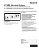


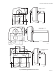
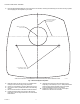

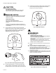
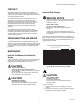

Table Of Contents

UV100A ULTRAVIOLET SYSTEMS
68-0248—4 4
Surface Treatment System
When installed next to the cooling coil, the Ultraviolet Surface
Treatment System prevents a high percentage of the growth of
micro-organisms such as mold that may grow on duct
surfaces, coils and drain pans. Individual results depend on
careful installation and maintenance. See. Fig. 2.
Fig. 2. Typical Surface Treatment installations.
IMPORTANT
If mounting options are limited, protect plastic or
rubber materials listed in CAUTION with ultraviolet-
resistant material such as aluminum foil duct tape.
NOTE: When the installer is uncertain about whether the drip
pan in the installation can tolerate UV exposure,
consult the UV exposure white paper, form no.
50-8788, at hbctechlit.honeywell.com Web site.
1. The UV System can be mounted in any orientation.
2. Choose a location that is readily accessible for regular
inspection and cleaning.
3. Allow clearance in front of the device for removing the
bulb assemblies. See Fig. 3 for bulb assembly lengths.
4. Mount the UV System to non-lined metal ductwork. Do
not mount in a location that permits ultraviolet exposure
to plastic flexible duct liner.
CAUTION
Sharp Edges Hazard.
Can cause personal injury.
Be careful when inserting ultraviolet device into the
sheet metal cutout.
Wear protective gloves when working near sheet metal.
Duct Mounting
Use the following instructions to mount the UV System on the
air duct of an HVAC system:
1. Disconnect power to the HVAC system before installing
the UV System.
2. Determine the location for installation (see Fig. 1 and 2):
a. The UV Air Treatment System requires an easily-
accessible, flat mounting surface on the metal return
air duct of the HVAC system. The UV Surface
Treatment System requires an easily-accessible, flat
mounting surface on the metal supply air duct of the
HVAC system. The UV Surface Treatment System
must be located so the lamp surrounds the
evaporator coil and drip pan with ultraviolet light.
b. The duct mounting location must be a minimum of
8 in. wide. See Fig. 3.
c. The depth of the duct must accommodate the full
length of the ultraviolet bulb for your model as shown
in Fig. 3.
d. The unit should be located as far away as possible
from any rubber or plastic components, such as
isolators, in the duct.
e. The space adjacent to the mounting location must be
large enough to allow for ultraviolet bulb installation
and removal.
f. A 120V or 240V electrical outlet must be within range
of the unit to plug in the power cord.
M22859
W
A
R
N
IN
G
/A
VE
R
TIS
S
E
M
E
N
T
!
Noc
ifs
pour la pe
au
nue et l
es
V
e
u
ille
z
lir
e
e
t
b
i
en
c
o
m
p
r
e
n
d
re
l’in
sta
lla
t
io
n
e
t la
m
a
in
ten
a
n
c
e
.
WARNING/AVERTISSEM
ENT
!
N
o
c
if
s p
o
u
r
l
a
p
e
a
u
n
u
e
et
l
e
s
Veuille
z l
ire et bien compr
end
re
l’in
stal
latio
n et
la
ma
int
enanc
e.