
Submittal Sheet


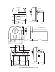

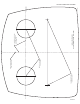
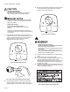


Table Of Contents

UV100A ULTRAVIOLET SYSTEMS
68-0248—4 6
3. Place the appropriate template for your model on the duct surface, centering the bulb hole(s) on the duct. See Fig. 4 (below
and next page) for the template for your model.
Fig. 4. Ultraviolet System templates.
4. Mark the location on the duct for the 2 in. diameter bulb
hole(s) and the unit mounting-screw pilot holes.
5. Cut the 2 in. bulb hole(s) in the duct. Remove any burrs.
6. Use a 3/32 in. drill to provide pilot holes for the mounting
screws.
7. Be sure the duct surface is flat after all holes are drilled.
8. Position the entire base unit on the duct. Be sure the
bulb holes in the duct align with those in the unit to allow
bulb insertion.
9. Install the unit into the duct using the three (or two,
depending on the model) no.10, 2 in. Phillips head sheet
metal mounting screws provided. (There is a spare
screw provided for the three-screw model.)
10. Tighten the screws to 12 to 14 in.-lb. so the space
between the case and duct is sealed.
M17664B
CENTER OF 2 IN. (51 MM)
HOLE FOR LAMP
3/32 IN. (3 MM) PILOT HOLES
FOR MOUNTING SCREWS
ALIGN EITHER OF THESE LINES
AS CLOSE AS POSSIBLE TO
DUCT CENTER LINE
INSTALLATION TEMPLATE FOR AIR TREATMENT SYSTEM (SINGLE LAMP) AND SURFACE TREATMENT SYTEM.