
Install Instructions
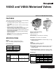
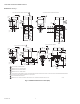
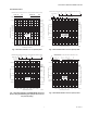
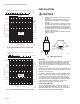
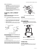
Table Of Contents

V4043 AND V4044 MOTORIZED VALVES
5 95C-10206—02
SWEAT COPPER MODELS
1. Use new, properly reamed pipe, that is free from dents
or corrosion.
2. Place valve onto pipe. Set the manual opener lever to
MAN. OPEN before applying heat. This will protect the
plug inside the valve by removing it from the heat.
3. IMPORTANT: Take care not to burn plastic portion of
composite adapter plate when soldering.
4. Sweat joints, but keep the outer surface free from sol-
der. DO NOT use silver solder because of the high melt-
ing temperatures it requires.
TO INSTALL REPLACEMENT
HEAD
REMOVING REMOVABLE HEAD FROM REMOVABLE
HEAD VALVE BODY ASSEMBLY
NOTE: It is not necessary to drain the system if the remov-
able head valve body assembly remains in the pipe-
line.
1. Switch power supplies OFF. Disconnect electrical leads,
carefully noting the position and colour of each lead.
2. Place the manual operating lever in the MAN. OPEN
position. See Fig. 9A.
3. Remove cover. See Fig. 9. Remove the two screws that
secure the head to the valve body assembly. (Fig. 9B.)
Fig. 9. Removing Cover.
INSTALLING REMOVABLE HEAD ON REMOVABLE HEAD
VALVE BODY ASSEMBLY
1. Place manual operating lever on the replacement head
in the MAN. OPEN position and fit the head onto the
valve body, ensuring that the shaft seats correctly. See
Fig. 10.
2. Secure the head to the valve body with the two screws
provided.
3. Remake wiring connections.
Inspect the head installation and the valve body to ensure that
all connections and adjustments have been correctly made.
Adjust the thermostat or controller connected to the valve so
that the valve runs through its cycle. Make sure the valve runs
smoothly and positively from closed to open to closed again.
Fig. 10. Installing Replacement Head.
WIRING
All wiring must agree with local codes and ordinances.
CAUTION
Ensure that all wires are properly dressed and
secured before replacing cover to avoid damage
to the insulation.
Fig. 11. Typical Wiring for V4043A, V4044A.
OPERATION
AUTOMATIC OPERATION
On a call for heat by the zone thermostat, the valve opens.
When the call for heat ends, the valve closes by integral
spring return.
SECURING
SCREWS (2)
M27944
MANUAL
OPERATING
LEVER
PORT A
PORT B
REMOVABLE
HEAD VALVE
BODY ASSEMBLY
SHAFT
MATING
RECESS
REMOVABLE
HEAD
BRASS
ADAPTER
PLATE
SHAFT
MOTOR
THERMOSTAT
(TYPICALLY T6069)
M16863
L1
(HOT)
L2
1
POWER SUPPLY. PROVIDE DISCONNECT MEANS AND
OVERLOAD PROTECTION AS REQUIRED.
1