
Install Instructions
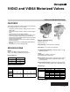
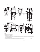
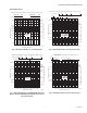
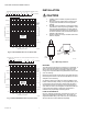
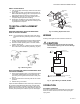

Table Of Contents

V4043 AND V4044 MOTORIZED VALVES
95C-10206—02 4
Fig. 6. Flow Characteristics of 7 Cv (6 kv) valve.
Fig. 7. Flow Characteristics of 8 Cv (6.9 kv) valve.
INSTALLATION
CAUTION
1. Installer must be a trained, experienced service
technician.
2. Disconnect power supply before connecting wir-
ing to prevent electrical shock and equipment
damage.
3. Normally it is not necessary to remove the power-
head from the valve body during installation. If the
valve must be disassembled, be certain that it is
reassembled with the water flow in the direction of
the arrow. Reversal of the powerhead will result in
damage to the gear train.
4. Always conduct a thorough checkout when instal-
lation is complete.
Fig. 8. Mounting Positions.
MOUNTING
The valve may be mounted in any position on a vertical line. If
valve is mounted horizontally, the powerhead must be even
with or above the center line of the piping. Make sure that
enough room is provided above the powerhead to remove the
cover for servicing.
Mount the valve directly into the tube or pipe. Make sure that
flow through the valve is in the direction indicated by the arrow
stamped on the valve body.
On diverting valves, the 3 fittings or ports are labeled on the
bottom of the valve body casting. In many applications, port A
is connected to the coil unit and is closed when the valve is
de-energized. Port B is connected to the coil bypass and is
open when the valve is de-energized. Port AB is the inlet and
is open at all times. Refer to equipment manufacturer’s
instructions for proper fitting of diverting valves.
FLARE FITTING MODELS
Use new, properly reamed pipe, that is free from chips. The
valve body is threaded for standard 1/2 in. OD copper, 45
degrees SAE flare fitting nuts. These nuts are not furnished
with the valve and must be obtained separately.
PRESSURE DROP, EQUIVALENT FEET OF PIPE (EQUIVALENT METERS OF PIPE)
2.0
(0.6)
3.0
(0.9)
3.5
(1)
21
(6.4)
24
(7.3)
25
(7.6)
22
(6.7)
23
(7)
20
(6)
19
(5.8)
17
(5.2)
15
(4.6)
13
(4)
10
(3)
-50 (149)
-40 (119)
-30 (89.5)
-20 (60)
(3/4 IN. PIPE)
(1/2 IN. PIPE)
50.0 (345)
10.0 (69)
5.0 (34)
1.0 (7)
0.50 (3.4)
0.10 (0.69)
0.05 (0.34)
0
2
(0.13)
4
(0.25)
6
(0.38)
8
(0.5)
10
(0.63)
12
(0.76)
14
(0.88)
16
(1.0)
18
(1.1)
20
(1.3)
22
(1.4)
24
(1.5)
26
(1.6)
28
(1.8)
30
(1.9)
-0.05 (0.15)
-.1 (0.3)
-.5 (1.5)
-1 (3)
-5 (15)
-10 (30)
M9185A
GAL/MIN (l/s) FLOW RATE
FT OF WATER psi (kPa)
PRESSURE DROP psi (kPa)
7CV
(6.0 KV)
PRESSURE DROP, EQUIVALENT FEET OF PIPE (EQUIVALENT METERS OF PIPE)
2.0
(0.6)
2.5
(0.8)
1.5
(0.5)
19
(5.8)
17
(5.2)
18
(5.5)
15
(4.6)
16
(4.9)
14
(4.3)
10
(3)
12
(3.7)
13
(4)
8
(2.4)
1
(3.4)
9
(2.7)
7
(2.1)
-50 (149)
-40 (119)
-30 (89.5)
-20 (60)
(3/4 IN. PIPE)
(1/2 IN. PIPE)
50.0 (345)
10.0 (69)
5.0 (34)
1.0 (7)
0.50 (3.4)
0.10 (0.69)
0.05 (0.34)
0.01
0
2
(0.13)
4
(0.25)
6
(0.38)
8
(0.5)
10
(0.63)
12
(0.76)
14
(0.88)
16
(1.0)
18
(1.1)
20
(1.3)
22
(1.4)
24
(1.5)
26
(1.6)
28
(1.8)
30
(1.9)
-0.05 (0.15)
-0.1 (0.3)
-0.5 (1.5)
-1 (3)
-5 (15)
-10 (30)
M9186A
GAL/MIN (l/s) FLOW RATE
FT OF WATER psi (kPa) PRESSURE DROP
PRESSURE DROP psi (kPa)
8CV
(6.9 KV)
M10162
A
VERTICAL
PIPING
HORIZONTAL
PIPING