
Install Instructions
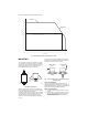
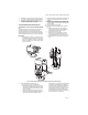
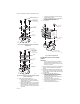
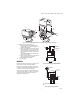
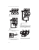
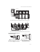
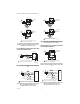
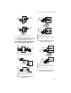
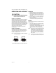
Table Of Contents

V4043, V4044 VALVES; V8043, V8044 ZONE VALVES
5 95-6983—11
Fig. 7. Remove old powerhead cover from systems using new style valve bodies.
4. Install the new powerhead (see Fig. 6):
a. Place the manual opening lever (normally
closed models only) on the new powerhead in
the MAN. OPEN position.
b. Fit the powerhead onto the valve body, ensuring
that the shaft seats correctly. The powerhead
should be aligned so that the manual opening
lever or slot for lever is at the port A end of the
valve body.
c. Secure the powerhead to the valve body with
the two screws provided.
d. If fitted, reconnect the conduit or cable. Recon-
nect the leadwires to the powerhead.
e. Replace the powerhead cover.
5. Turn on the power.
WIRING
Disconnect the power supply before connecting wiring to
prevent electrical shock or equipment damage.
All wiring must comply with local codes and ordinances.
Connections to the individual valves are shown in Fig. 8-
9. See Fig. 10 through 16 for typical hookups.
If replacing a Taco, Dole, Flair or White Rodgers 3-wire
valve with a 2-wire V8043E or F, see Fig. 17 through 29.
Check that the pressure rating of the new valve is
appropriate for the application.
Fig. 8. Typical wiring for V8043E, V8044E.
Fig. 9. Typical wiring for V8043F.
A
AUTO
MAN
OPEN
MANUAL
OPENING
LEVER
COVER
RETAINING
SCREW
M10161
A
B
B
V8043F 1036
24V 50/60 CY
.32 AMP @ 60 CY
MADE IN CANADA
6
A
B
AUXILIARY
SWITCH
MOTOR
YELLOW
LEADS
TO CIRCULATOR
OR ANOTHER VALVE
RED LEADS
THERMOSTAT
(TYPICALLY T87F)
TO
LINE
M5953
R
L1
(HOT)
L2
1
1
POWER SUPPLY. PROVIDE DISCONNECT MEANS AND
OVERLOAD PROTECTION AS REQUIRED.
END SWITCH
TO CIRCULATOR
OR ANOTHER
VALVE
TH
TR
24V
TRANSFORMER
THERMOSTAT
(TYPICALLY T87F)
TH TR
M5952