
Install Instructions
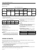
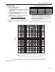
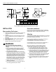
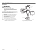


Table Of Contents

V4046C, V8046C MAGNETIC VALVES
5 66-2008—3
Fig. 3. Preparing the pipe threads.
Gas and Air Applications
Test for leaks by painting pipe joints with a soapy solution.
Excessive bubbles indicate a leak.
WIRING
WARNING
Electrical Shock Hazard.
Can cause serious injury or death.
Disconnect power supply before wiring to prevent
electrical shock or equipment damage. More than one
disconnect can be involved.
All wiring must conform to local codes and ordinances.
Leadwires on these devices are long enough to reach the
junction box on most burner installation. The powerhead on all
models rotates 360 degrees, permitting the electrical service
to be brought to it from any convenient direction.
See Fig. 4 and 5 for typical wiring hookups for V4046C and
V8046C, respectively.
Fig. 4. Typical hookup of V4046C. See Flame Safeguard
wiring diagram to determine correct terminal for pilot
valve connection.
Fig. 5. Typical hookup of V8046C.
CHECKOUT AND SERVICE
Checkout
Put the system in operation and observe through at least one
cycle to be sure valve functions as described.
NOTE: Valve clicks audibly when it opens and when it
closes. Listen for clicks to make sure valve is
opening and closing properly.
Service
IMPORTANT
Do not assume that the valve needs replacement
until all other sources of trouble have been
eliminated.
If the valve will not open when the thermostat and
limit control are calling for heat:
1. Make sure that the pilot is burning properly, the
Pilotstat® Control (if used) is holding in, and the limit
control contacts are closed.
2. Make sure that normal gas pressure is available at the
valve.
3. Make sure that the bleed line is unobstructed.
4. Check the power supply at the valve. If no voltage is
indicated, check the power source (transformer or line
source) and circuit controls. If proper voltage is present
at the valve, but the valve does not pull in, replace the
valve coil.
If the valve will not close with one or more of the
control contacts open:
1. Make sure that the gas flow is in the direction of the
arrow on the valve body.
2. Check for a short in the wiring circuit.
INCORREC
T:
TWO CLEAN
THREADS,
MODERATE
AMOUNT
OF DOPE
EXCESS DOPE MAY BLOCK
DISK OFF
VALVE
SEAT
LOOSE
CHIPS
CORRECT:
NORMAL
FULL
THREAD
TOO LONG
,
DISTORTS
VALVE SEA
T
M20744
1
1
USE PIPE DOPE RESISTANT TO ACTION OF LP GAS.
FLAME
SAFEGUARD
CONTROL
M20745
V4046C
PILOT VALVE
NEUTRAL SIDE OF
POWER SUPPLY
1
1 PROVIDE DISCONNECT MEANS AND OVERLOA
D
PROTECTION AS REQUIRED.
L1
(HOT)
L2
M20746
P
OWER SUPPLY. PROVIDE DISCONNECT MEANS
A
ND OVERLOAD PROTECTION AS REQUIRED.
V4046C
PILOT VALVE
CONTROLLER
AT20 (OEM MODEL)
OR AT30
24V 60 HZ TRANSFORMER