
Install Instructions
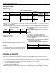
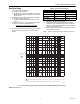
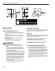
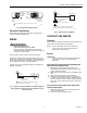
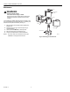


Table Of Contents

V4046C, V8046C MAGNETIC VALVES
66-2008—3 4
Fig. 2. V4046C, V8046C approximate dimensions in in. (mm).
INSTALLATION
When Installing This Product…
1. Read these instructions carefully. Failure to follow them
could damage the product or cause a hazardous
condition.
2. Check the ratings given in the instructions and on the
product to make sure the product is suitable for your
application.
3. The installer must be a trained, experienced flame
safeguard technician.
4. After installation is complete, check out product
operation as provided in these instructions.
WARNING
Explosion and Electrical Shock Hazard.
Can cause serious injury, death or property
damage.
1. Turn off gas supply before beginning installation.
2. Disconnect electrical power before beginning
installation or servicing procedure. More than one
disconnect can be involved.
3. To avoid damage or distortion of the valve when
installing rigid or flexible conduit, the conduit fittings
should not be subjected to more than 5 ft-lbs torque
when screwing the fitting into the valve coil case
(powerhead). An approximation of 5 ft-lbs torque is
hand-tightened plus 1/8 turn. When securing the
rigid or flexible conduit in the conduit fitting using
the setscrew, use only enough force to secure the
conduit to avoid damage/distortion of the valve.
4. Always loosen the coil nut before attempting to
rotate the powerhead.
5. Do not tighten the valve on the gas pipe using the
coil housing (powerhead) as a handle.
Gas and Air Installations
Mount the gas valves in the pilot gas supply line upstream
from the burner. Ambient temperatures at the valve location
must be within -40°F to +125°F (-40°C to +54°C).
Mounting
The V4046C and V8046C Valves will operate in any mounting
position required by the installation, as long as gas flow is in
the direction indicated by the arrow.
Use iron pipe for at lease one of the valve connections to
insure adequate support and to confirm with
recommendations of Underwriters Laboratories, Inc.
If the installation does not support the valve adequately, a
mounting bracket should be devised and installed.
Preparing Piping and Installing Valve
1. Use new, properly reamed pipe, free from chips.
2. Do not thread pipe too far. Valve distortion or valve
malfunction may result from excess pipe in valve.
3. Apply a moderate amount of good quality pipe dope to
the pipe only (see Fig. 3). If pipe dope lodges on the
valve seat, it will prevent proper closure. If using LP
gas, use pipe dope resistant to action of LP gas.
4. Install the valve with gas flow in the direction indicated
by the arrow on the valve body. Gas must be in the
same direction as indicated by the arrow.
5. Move the powerhead to the desired position and then
tighten the hexagonal nut located on the top of the
valve.
1-3/16
(30)
DIM. A
1-3/8
(35)
1-5/8
(41)
1-3/4 (45)
2-5/8 (67)
1-3/4 (45)
DIM. B
1-1/4 (32)
BASIC
CENTER
45°
BASIC
CENTER
8-32 x 1/4 IN.(6)
DEEP (2)
1/2-14 NPSM
36 IN. (915)
LEADS (2)
SEE TAB
MODEL
V4046C,
V8046C
BODY
SIZE
THREAD
SIZE
SMALL
SMALL
LARGE
LARGE
1/8-27 NPT
1/4-18 NPT
1/4-18 NPT
3/8-18 NPT
5/16
3/8
1/2
1/2
8
10
13
13
2-3/4
3
3-1/4
3-1/4
70
76
83
83
DIM. A DIM. B
IN MM IN MM
M16595