
User Guide

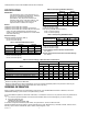
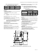
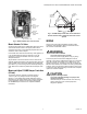
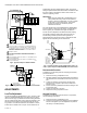
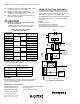
Table Of Contents

V4062A,B,D HI-LO-OFF FLUID POWER GAS VALVE ACTUATOR
60-2099—10 4
Table 7. Approximate Mounting Dimensions of V4062 Actuators with V5055 and V5097 Valves.
a
Valve size using accessory pipe adapter fitting.
INSTALLATION
When Installing This Product…
1. Read these instructions carefully. Failure to follow
them could damage the product or cause a hazardous
condition.
2. Check the ratings given in the instructions and on the
product to make sure the product is suitable for your
application.
3. Installer must be a trained experienced, flame
safeguard control technician.
4. After installation is complete, check out product
operation as prided in these instructions.
WARNING
Electrical Shock Hazard.
Can cause serious injury or death.
Disconnect power supply before making wiring
connections to prevent electrical shock and
equipment damage.
IMPORTANT
1. All wiring must comply with all applicable electrical codes,
ordinances, and regulations. All wiring must be NEC
Class 1.
2. Voltage and frequency of the power supply connected to
this control must agree with those marked on the device.
3. Loads connected to the auxiliary switch and/or
proof-of-closure switch, if used, must not exceed the
ratings given in the Specifications section.
4. When replacing a V6034 Actuator with a V4062, the
V5034 Valve body must be changed to a V5055 Valve.
5. Do not attempt to use the V4062 Actuator with the V4055/
V5034 Adapter. Differences in stem travel can prevent
correct low fire adjustment.
Install Valve
The actuator is installed directly on the V5055/V5097 body
after the valve is installed in the gas supply line. Refer to the
instructions packed with the V5055/V5097 Gas Valve for
installation details. When installing the valve, assure that:
1. Sufficient clearance is allowed for actuator installation
and service.
2. Ambient temperatures at the valve location do not
exceed actuator ratings.
3. Position of the valve permits damper hookup if one is
controlled.
Install Accessory Switches (If Needed)
An spdt switch can be installed to operate an auxiliary load up
to 1/2 hp (0.37 kW). The switch can be adjusted to operate at
any point in the valve stroke.
A proof-of-closure switch can also be installed with a V5055/
V5097C or E Valve (with double seal) on any V4062 Actuator
to provide a valve seal overtravel interlock. The spdt proof-of-
closure switch is installed to make or break a circuit when the
valve is in the closed position. The switch is not adjustable.
NOTE: Mark the actuator or valve to indicate any changes
made.
To install the switches, proceed as follows:
1. Remove the actuator faceplate (two screws).
2. Remove the silver-colored barrier to expose the actuator
stem.
3. Insert the auxiliary switch in the position indicated in Fig.
2. Fasten with two screws through the actuator base.
4.
Insert the proof-of-closure switch in the position shown in
Fig. 2. The proof-of-closure switch mounts against the side
of the actuator housing. The mounting holes are spaced to
allow mounting the switch only in the correct position.
Fasten with two screws through the actuator base.
5. If only one switch is used, install the narrow barrier
included with the switch in the unused space.
6. Mount the actuator before making wiring connections
and adjustments to the auxiliary switch.
Valve Size
a
(in.)
V5055 V5097
Dim. A Dim. B Dim. C Dim. D Dim. A Dim. B Dim. C Dim. D
in.mmin.mmin.mmin.mmin.mmin.mmin.mmin.mm
Small
Body
3/4 11-1/8 283 2-3/4 70 8-3/16 208 5-3/4 146 11-1/8 283 2-3/4 70 8-3/16 208 2-1/2 64
1 11-1/8 283 2-3/4 70 8-3/16 208 5-3/4 146 11-1/8 283 2-3/4 70 8-3/16 208 2-/12 64
1-1/4 11-1/8 283 2-3/4 70 8-3/16 208 5-3/4 146 11-1/8 283 2-3/4 70 8-3/16 208 2-1/2 64
1-1/2 11-1/8 283 2-3/4 70 8-3/16 208 5-3/4 146 11-1/8 283 2-3/4 70 8-3/16 208 2-1/2 64
2 11-1/8 286 2-7/8 73 8-5/16 211 8-3/8 213 11-3/4 298 3-3/8 86 8-3/8 213 4 102
Large
Body
2 11-3/4 298 3-3/8 86 8-13/16 224 9-1/4 235 11-3/4 298 3-3/8 86 8-3/8 213 4 102
2-1/2 11-3/4 298 3-3/8 86 8-13/16 224 9-1/4 235 11-3/4 298 3-3/8 86 8-3/8 213 4 102
3 11-3/4 298 3-38 86 8-13/16 224 9-1/4 235 11-3/4 298 3-3/8 86 8-3/8 213 4 102
4 14-1/83595-13/1614811-7/3228512-1/2318————————