
User Guide

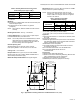
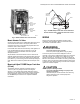
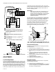
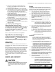
Table Of Contents

V4062A,B,D HI-LO-OFF FLUID POWER GAS VALVE ACTUATOR
5 60-2099—10
Fig. 2. V4062 Actuator with cover removed.
Mount Actuator On Valve
Check the final position of the V5055/V5097 Valve body to be
sure that the actuator will be in the proper position when
mounted on the valve. This is especially important when the
actuator is used to drive a damper.
If two smaller size valves are mounted very close together, as
in an Industrial Risk Insurers type valve train, it may be
necessary to mount the actuators off center to provide
adequate clearance.
Slip the bottom collar of the actuator over the valve bonnet
assembly. Rotate the actuator to the desired position and use a
5/32-inch Allen wrench to securely tighten the two setscrews
(50 to 60 lb-in. [5.7 to 6.8 N•m]). Connect the damper linkage, if
used. Refer to the instructions packed with the damper crank
arm.
Mount and Adjust 7616BR Damper Crank Arm
(If Used)
The damper crank arm provides a maximum travel of
2-5/16 in. (58.7 mm) through a stroke of 52 degrees.
See Fig. 3. If the V4062 has a damper shaft return spring,
dampers go to the closed position when power is interrupted
by the programmer. Refer to the instructions packed with
the 7616BR Damper Crank Arm for complete installation
information.
Fig. 3. 7616BR Damper Crank Arm can be attached to
actuator shaft to drive a damper at same time valve is
opened.
WIRING
Wiring must comply with all applicable electrical codes,
ordinances, and regulations. Wiring to the actuator and to
the controller must be NEC Class 1.
WARNING
Electrical Shock Hazard.
Can cause serious injury or death.
Disconnect power supply before doing any wiring.
Connect the power from the flame safeguard control to
terminals 1 and 2 on the V4062 terminal strip, and connect the
firing rate controller to terminals 3 and 4. Refer to Fig. 4 for
typical connection. Fig. 5 shows the wiring for connecting the
Max Flow Limit Switch to the actuator. For other typical system
hookups, refer to the instructions packed with the device used
to control the valve. When all wiring connections are complete,
replace the actuator faceplate.
CAUTION
Equipment Damage Hazard.
Can cause equipment damage or improper and
dangerous operation.
Label all wires prior to disconnection when servicing
valves. Wiring errors can cause improper and
dangerous operation.
133568
AUXILIARY
SWITCH
133569
VALVE-CLOSED
INDICATION
SWITCH
AUXILIARY
SWITCH
ADJUSTMENT
SCREW
LOW-FIRE
ADJUSTMENT CAM
M7338B
52 DEGREE
ANGULAR
ROTATION
MAXIMUM
TRAVEL
SHAFT
7616BR
DAMPER
ARM
M7322
RADIUS
2-11/16 (68.3)
2-5/16 (58.7)