
User Guide

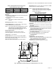
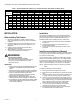
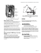
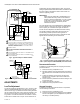
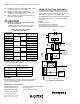
Table Of Contents

V4062A,B,D HI-LO-OFF FLUID POWER GAS VALVE ACTUATOR
60-2099—10 6
Fig. 4. Typical hookup for V4062 Actuator.
Fig. 5. Connecting Max Flow Limit Switch to the actuator.
ADJUSTMENTS
Low-Fire Adjustment
The low-fire position is adjustable from 0.16 in. to 0.64 in. (with
respect to V5055/V5097B Valve) valve stem travel. A dial on
the low-fire cam (Fig. 6) indicates the low-fire setting. Because
the cam rotates as the valve opens, scales are marked on the
dial so the low-fire setting can be observed with the valve in
any position. One scale is visible when the actuator is closed,
and the other is visible when it is open. These scales are not
independent; the same setting applies to both. The low-fire
setting is adjusted either before the actuator is installed or after
the entire system is operational. Refer to form 70-8311 for
valve flow (capacity) curves.
IMPORTANT:
When using the V4062 with a V5055/V5097C or E
Valve (with double seal), match low-fire minimum
position to burner and application. Too low a position
could result in loss of burner flame. This low-fire
position should also be checked at periodic
maintenance intervals.
For most effective use of the V4062/V5055 or V4062/V5097,
be sure to select a valve body size closely corresponding to
burner capacity. An oversized valve might not allow the
low-fire rate to be adjusted to the desired minimum setting.
The V4062 Actuator is shipped from the factory with the
low-fire setting at MAX to provide a valve gas flow of
approximately 50 to 60 percent, which is adequate for safe
lightoff until the final setting can be determined.
Fig. 6. Low-fire position can be adjusted from 0.16 in. to
0.64 in. (with respect to V5055/V5097B) valve stem travel.
Recommended Procedure
To adjust the low-fire setting without energizing the actuator,
proceed as follows:
1. Remove the wiring compartment cover.
2. Manually rotate the cam and dial assembly downward so
that the setscrew is accessible from the front of the actu-
ator.
3. Loosen the setscrew on the low-fire cam using the
special wrench (supplied—taped to the inside of the
actuator cover).
4. Set the cam to the predetermined low-fire setting for the
burner being used.
5. Tighten the setscrew in the cam.
6. Replace the wiring compartment cover.
Alternate Procedure
To adjust the low-fire setting after the burner is in operation,
use the following instructions:
1. Remove the wiring compartment cover.
2. Check to be sure the low-fire adjustment is set at MAX to
assure a safe lightoff. (Low-fire adjustment is preset at
the factory in the MAX position.)
2
1
4
3
5
6
2
1
34
AUXILIARY
SWITCH
L1
HOT L2
POWER FROM FLAME SAFEGUARD CONTROL.
ACTUATOR OPENS TO LOW-FIRE POSITION WHEN FIRING RATE
CONTROLLER SWITCH IS OPEN AND LINE VOLTAGE IS SUPPLIED
TO TERMINALS L1 AND L2. ACTUATOR OPENS FULLY WHEN THE
FIRING RATE CONTROLLER SWITCH IS CLOSED AND POWER IS
SUPPLIED TO TERMINALS L1 AND L2.
3
INTERNAL JUMPER.
4
FOR LOW-FIRE ADJUSTMENT AFTER BURNER IS IN OPERATION.
DISCONNECT FIRING RATE CONTROLLER LEADWIRE FROM
TERMINAL 4.
5
SWITCH BETWEEN THESE TWO LEADS IS CLOSED WHEN VALVE IS
SHUT (DE-ENERGIZED).
6
SWITCH BETWEEN THESE TWO LEADS IS OPEN WHEN VALVE IS
SHUT (DE-ENERGIZED).
NO
NC
C
NO
NC
C
5
6
1
2
L2
FIRING
RATE
CONTROLLER
FLAME SAFEGUARD
PROGRAMMER–MAIN
VALVE CONNECTIONS
PROOF-OF-
CLOSURE SWITCH
M7339
M12798
C
7800 SERIES
RELAY
MODULE
NC
NO
ADJUSTABLE
MAX
FLOW
LIMIT
SWITCH
FIELD WIRING
INTERNAL WIRING
TRAVEL
LIMIT
SWITCH
PUMP
MOTOR
PUMP
VALVE
1
L2
9
2
34
MAX
MAX
E
LOW-
FIRE
CAM
MIN
D
C
B
A
LO FIRE
SETSCREW
DUAL
LOW-FIRE
SETPOINT
INDICATORS
(SHOWN AT
MAX WITH
VALVE OPEN)
DIAL
M7340