
User Guide

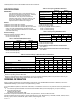
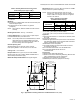
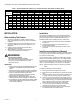
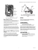
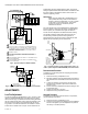
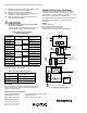
Table Of Contents

V4062A,B,D HI-LO-OFF FLUID POWER GAS VALVE ACTUATOR
7 60-2099—10
3. Disconnect the firing rate controller leadwire from
terminal 4 on the actuator to keep the valve in the
low-fire position (Fig. 4).
4. Start the system and establish the main burner flame.
5. Loosen the setscrew in the cam (Fig. 5) with the special
wrench. Keep the wrench seated in the setscrew. Rotate
the cam slightly downward (by moving the wrench
toward the actuator base) to open the bleed valve. The
actuator will start to close.
6. When the valve reaches the desired low-fire position,
quickly tighten the setscrew and remove the wrench.
If the desired low-fire setting is missed, loosen the
setscrew and rotate the cam in the opposite direction to
the desired setpoint.
7. Shut down the burner, and then restart. Repeat several
times to be sure the low-fire setting is suitable for correct
burner lightoff. Readjust, if necessary.
8. Disconnect power and reconnect the controller leadwire
removed in step 3.
9. Replace the wiring compartment cover.
Adjust Auxiliary Switch (If Used)
The auxiliary switch can be adjusted to operate at any point in
the actuator stroke. After installing the switch in the actuator,
turn the adjustment screw (Fig. 2) clockwise to cause
the switch to operate earlier in the stroke or turn
counterclockwise to cause the switch to operate later
in the stroke.
NOTE: The proof-of-closure switch is not adjustable.
Adjust Max Flow Limit Switch (Fig. 2)
The Max Flow Limit Switch is adjustable throughout the actuator
stroke. With the switch installed in the actuator, turn the
adjusting screw clockwise to cause the switch to operate
earlier in the stroke (less flow) or counterclockwise to
cause the switch to operate later in the stroke (more flow).
OPERATION
To function as intended, the V4062 must be connected to a
properly sized valve. Too large a valve will not properly control
the gas flow.
When the actuator is energized, it drives to the adjustable low-
fire position. Depending on the demand of the controller, the
valve remains at low-fire or moves to the high-fire position.
When the firing rate controller calls for no heat, the actuator
returns the valve to the low-fire position. When power to the
actuator is interrupted, the valve completely closes.
Fig. 4 shows the V4062 in a typical flame safeguard control
system.
SERVICE AND CHECKOUT
CAUTION
Equipment Damage Hazard.
Unskilled technicians can damage the equipment.
Only experienced, trained flame safeguard control
service technicians should service or replace this
control.
Service
The actuator is not field repairable, except for replacing the
auxiliary switch or valve-closed indication switch. See Installation
section for procedure. Do not disassemble the valve actuator. If
the actuator should fail to operate properly, replace it.
1. Turn off the gas supply at the manual shutoff valve
located upstream from the valve(s) being serviced.
2. Shut off all electrical power to the valve actuator(s).
3. Mark and disconnect the wires from the actuator termi-
nals. Remove conduit and disengage the damper link-
age assembly (if applicable).
4. Loosen the two set screws from the valve to lift off the
actuator.
5. If the actuator is to be replaced and it did not leak
hydraulic fluid, skip to Step 11.
NOTE: It is good practice to inspect the inside of the
valve whenever the actuator is replaced. To do
so, remove the bonnet assembly, inspect the
valve and bonnet. If all is well, proceed to Step 7.
6. If the actuator leaked hydraulic fluid onto the valve (the
fluid is red), it must be cleaned off from the valve and
bonnet assembly.
a. Wipe off the outer valve body.
b. Remove the valve bonnet bolts and lift off the bonnet.
NOTE: V5055/V5097C and E Valves have additional
internal springs that will push the bonnet up as
the bolts are loosened.
c. Inspect the inside of the valve.
IMPORTANT
If fluid is present on the inside surfaces of the valve
body or bonnet surfaces, the bonnet assembly or
entire valve must be replaced. See Table 8 below for
the bonnet assembly part number.
d. If the inside surfaces are clear of hydraulic fluid, clean
the bonnet assembly and be sure to remove all
hydraulic fluid from the inside and outside of the actu-
ator mounting curb. This is the “cup-like” area around
the valve stem. Avoid using a cleaning solution as it
may damage the rubber seals used in the valve.
7. If the valve bonnet assembly is in good condition and is
not replaced, replace the bonnet seal. Do not reuse the
old bonnet seal. See Table 9 below for the seal number.
8. Coat seals with grease provided and position in valve
body/bonnet assembly.
9.
Carefully seat the bonnet assembly on the valve body. Be
sure the seals are in their proper position. On those valves
with a spring below the disc, be sure the spring is centered
in the indentation on the inside of the valve body.
10. After positioning the bonnet assembly, replace the
screws removed earlier.
NOTE: When replacing the bonnet assembly on the 4-
inch valve, draw it evenly into the valve body.
Finger-tighten the eight bolts. Draw the bonnet
assembly into the valve by tightening, in order,
bolts 1, 5, 7 and 3 (two turns each). Repeat until
the bonnet assembly is seated. Tighten the
remaining bolts. Torque the bolts as follows:
Valve Size Torque
3/4 in. (19 mm) to 1-1/2 in. (38 mm) 55 in.-lb.
2 in. (51 mm) to 4 in. (102 mm) 75 in.-lb.