
User Guide

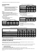
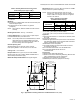
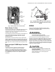
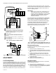
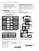
Table Of Contents

Automation and Control Solutions
Honeywell International Inc. Honeywell Limited-Honeywell Limitée
1985 Douglas Drive North 35 Dynamic Drive
Golden Valley, MN 55422 Toronto, Ontario M1V 4Z9
customer.honeywell.com
V4062A,B,D HI-LO-OFF FLUID POWER GAS VALVE ACTUATOR
® U.S. Registered Trademark
© 2007 Honeywell International Inc.
60-2099—10 M.S. Rev. 06-07
11. Remount the actuator on the bonnet assembly. Tighten
the two set screws (50-60 inch pounds).
12. Replace the damper crank arm assembly.
13. Re-attach the wires removed from the actuator termi-
nals and turn on the electrical power.
14. With the gas still off, cycle the actuator to check for
proper mechanical operation.
CAUTION
Be sure to perform a bonnet seal and seat leak
check after installation.
Be sure to read and follow all instructions that come
with the actuators, valves, seal and bonnet kits.
Each replacement assembly contains the bonnet assembly,
two rubber seals, and a tube of grease. It must be used only
on the type of valve indicated above.
Checkout
After the installation is complete, cycle the valve several times
with the manual fuel shutoff cock closed before testing the
system in actual operation.
V4062A1156 Fluid Power Gas Actuator
The V4062A1156 Fluid Power Gas Valve Actuator was
modified to provide modulation between high-and low-fire
positions when used with a Series 60 controller, such as the
W964 Aquatrol™ System and two auxiliary relays.
The V4062A1156 will not operate properly wired similarly to
other V4062 models. See Fig. 7 for suggested wiring
procedure.
Ratings:
Voltage: 120V, 60 Hz.
Nominal Opening Time: 26 seconds.
Closing Time: one second maximum.
See Specifications section for further specifications.
Fig. 7. Suggested wiring diagram.
Table 8. Replacement Bonnets for
V5055/V5097 Gas Valves.
Replacement
Bonnet Valve Valve Size (in in.)
133398AA V5055A V5097A 3/4, 1, 1-1/4, 1-1/2
133417AA 2, 2-1/2, 3
136911AA (On-Off) 4
133398BA V5055B V5097B 3/4, 1, 1-1/4, 1-1/2
133417BA 2, 2-1/2, 3
136911BA (Characterized Guide) 4
133398CA V5055C V5097C 3/4, 1, 1-1/4, 1-1/2
133417CA 2, 2-1/2, 3
136911CA (Proof of Closure) 4
136308AA V5055D V5097D 3/4, 1, 1-1/4, 1-1/2
136307AA 2, 2-1/2, 3
136308BA V5055E V5097E 3/4, 1, 1-1/4, 1-1/2
136307BA 2, 2-1/2, 3
Table 9. Gas Valve Replacement Seals.
Replacement Seal
Assy # Valve Size (in in.)
133393A 3/4, 1, 1-1/4, 1-1/2
133392A 2, 2-1/2, 3
137253A 4
2
1
1
1 2
2
L1
W964
R1 – NORMALLY CLOSED RELAY CONTACT.
R2 – NORMALLY OPEN RELAY CONTACT.
NO
NC
C
AUX.
SWITCH
R1
RELAY
CONTACT
R2
RELAY
CONTACT
TO MAIN VALVE
TEMINAL ON
PROGRAMMER
V4062
5
3 4 1
2
1 2
V4055
L2
L2
R2
RELAY
COIL
R1
RELAY
COIL
INDOOR
SENSOR
OUTDOOR
SENSOR
CBA
M7341