
Install Instructions


X-XX UL
INSTALLATION INSTRUCTIONS
®U.S. Registered Trademark
Copyright © 1998 Honeywell Inc. • All Rights Reserved
62-0152
V5011N, V5013N Two-Way and Three-Way
NPT Threaded Globe Valves
DESCRIPTION
V5011N valves are single-seated, two-way, straight-
through valves that provide control of steam, glycol
solutions (up to 50 percent concentration) and hot or
chilled water in HVAC systems requiring tight shutoff.
V5013N valves are three-way mixing valves that provide
proportional control of glycol solutions (up to 50 percent
concentration) and hot or chilled water in HVAC systems.
V5013N valves direct the flow from one of two inlets to a
common outlet (mixing).
V5011N and V5013N are suitable for actuation with
pneumatic actuators such as MP953; for actuation with
electric operators such as Modutrol IV Motors when used
with Q5001 linkage; for electric actuation using valve direct
coupled actuators such as ML6874, ML7984, ML6421,
ML7421, ML6425, and ML7425. Refer to actuator
specifications to determine dimensional, wiring and
mounting requirements for a particular actuator. Table 1
shows available size and flow capacities for the valves.
The stroke for both valves is 3/4 in. (20 mm).
Table 1. V5011N and V5013N Size and
Flow Capacities.
Valve Size (in.) V5011N (C
v
) V5013N (C
v
)
1/2—DN15 0.73 —
1/2—DN15 1.16 —
1/2—DN15 1.85 —
1/2—DN15 2.9 2.9
1/2—DN15 4.7 4.7
3/4—DN20 7.3 7.3
1—DN25 11.7 11.7
1-1/4—DN32 18.7 18.7
1-1/2—DN40 29.3 29.3
2—DN50 46.8 46.8
INSTALLATION
When Installing this Product . . .
1. Read these instructions carefully. Failure to follow
them could damage the product or cause a hazard-
ous condition.
2. Check the ratings given on the instructions and on
the product to make sure the product is suitable for
your application.
3. Installer must be a train, experienced service
technician.
4. After installation is complete, check out product
operation as provided in these instructions.
IMPORTANT
1. Do not lift the valve by holding the stem.
2. Mount the valve body with the stem upright to
90 degrees from vertical. Do not mount the valve
with the stem pointed lower than horizontal.
3. Mount the valve with the flow arrow pointed in the
direction of flow through the valve.
4. Mount the valve between pipes which are in line.
Mounting the valve on pipes that are not aligned
causes leakage at the valve to pipe connection.
5. Ensure complete engagement on pipe to valve
body threads.
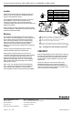
6. Hold the valve body with a clamp or pipe wrench
on the hexagonal fitting nearest the pipe to
prevent damage to the valve body while mount-
ing on the pipe. Refer to Fig. 1.
7. Be sure to allow enough room for installation and
service. Clearance for installation of the valve is
dependent on the size of the actuator and the
pipe size of the valve.