
Install Instructions

62-0152
2
V5011N, V5013N TWO-WAY AND THREE-WAY NPT THREADED GLOBE VALVES
Home and Building Control
Honeywell Limited-Honeywell Limitée
155 Gordon Baker Road
North York, Ontario
M2H 3N7
62-0152 G.S. 5-98
Home and Building Control
Honeywell Inc.
Honeywell Plaza
P.O. Box 524
Minneapolis, MN 55408-0524
www.honeywell.com
Location
Select a location where the valve, linkage (if used), and
actuator to be used are within the appropriate ambient
pressure and temperature ratings.
Leave sufficient clearance above the valve to accommo-
date installation of the actuator and allow room for
servicing the valve body. (The valve body should be
completely installed in the pipe line before the actuator and
linkage are installed.)
When selecting a location for the valve, consider actuator
mounting restrictions. Most Modutrol IV Motors require that
shafts be mounted horizontally.
Mounting
The preferred mounting position of the valve is with the
stem vertical. For steam applications, mount with the stem
at a 45 degree angle. Do not mount the valve with the
stem more than 90 degrees from the vertical (pointing
lower than horizontal). Scale and foreign material can
collect and can score the stem and cause packing
leakage. Protect the stem from damage due to bending or
scratching.
V5011N, V5013N screwed body threads conform to
American Standard Taper Pipe Threads (NPT).
Align the pipes squarely with the valve at each end
connection. If the pipes are forced into the valve, the body
can become twisted and improper seating can result.
Apply pipe dope sparingly. Be careful to prevent pipe
debris such as pipe chips, scale, etc., from entering the
piping because this material can lodge in the seat and
prevent proper closing.
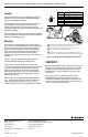
Refer to Fig. 1 for valve pipe sizes and thread lengths.
Fig. 1 also shows two effective methods of holding the
valve and pipe when attaching it. The valve will not
function properly if twisted or squeezed during installation.
Fig. 1. Installing valve with threaded connections.
CHECKOUT
Before installing linkage (if used) and actuator, make sure
that valve stem operates freely. Impaired stem operation
can indicate that the body was twisted or that the stem
was bent. Either of these conditions may require valve
replacement.
Check valve body and connections for leaks. After
installing linkage and actuator, check the operation
according to installation information provided with these
controls. Operate the system through one complete cycle
to be sure the valve controls properly.
USE VISE GRIPS WITH THE HEX END NEXT TO THE PIPE
(DO NOT TWIST OR SQUEEZE VALVE BODY).
USE VISE TO HOLD PIPE SECURELY TO PREVENT TURNING. USE
PARALLEL-JAW WRENCH TO GRIP VALVE HEX FLATS NEXT TO PIPE.
M11763A
USE PROPERLY REAMED AND CLEANED PIPE AND MODERATE
AMOUNT OF DOPE (LEAVE TWO THREADS BARE).
PIPE SIZE
(IN.)
1/2
3/4
1
1-1/4
1-1/2
2
EFFECTIVE LENGTH OF THREADS
IN IN. (MM)
1/2
9/16
11/16
11/16
11/16
3/4
(12.7)
(14.3)
(17.5)
(17.5)
(17.5)
(19.1)
1
1
2
2
3
3