
Product Overview

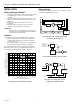

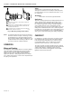


Table Of Contents

V5013B,C,F THREE-WAY MIXING AND DIVERTING VALVES
60-2129—4
5
Fig. 7. Typical zone hookup of V5013C diverting valve
used to control flow through coil.
Valve Installation
Threaded Valve bodies
Line up the pipes squarely with the valve at each end. If the
pipes are forced into the valve, the body may become twisted
and improper seating will result. Prevent pipe chips, scale,
and dirt from entering the piping since they may lodge in the
seat and prevent proper closing. Apply a vise or wrench to the
valve (see Fig. 9).
COIL
AB
A
B
V5013C
M11760
RETURN LINE TO
BOILER OR CHILLER
SUPPLY LINE FROM
BOILER OR CHILLER
Fig. 8. Three-way mixing valve operation–coil bypass.
Three-way valves maintain constant flow in the piping.
As the temperature requirements change, the
volume of the fluid in the coil varies.
AB A
B
M11761
HEATING COIL
FULL
HEAT
5 GPM
5 GPM
2.5 GPM
5 GAL./MIN.
AB A
B
PROPORTIONED
HEAT
2.5 GPM
SUPPLY
MAIN
RETURN
MAIN
5 GPM
5 GPM
AB A
B
NO
HEAT
NO FLOW
THROUGH COIL
A
B
C
VISE GRIPS HEX END NEXT TO PIPE (DO NOT TWIST OR
SQUEEZE VALVE BODY).
VISE HOLDS PIPE SECURELY AGAINST TURNING AND PARALLED
JAW WRENCH GRIPS VALVE HEX FLATS NEXT TO PIPE.
M11763
USE PROPERLY REAMED AND CLEANED PIPE AND MODERATE
AMOUNT OF DOPE (LEAVE TWO THREADS BARE).
PIPE SIZE
(INCHES)
1/2
3/4
1
1-1/4
1-1/2
2
EFFECTIVE LENGTH OF THREADS
(INCHES) [MILLIMETERS]
1/2
9/16
11/16
11/16
11/16
3/4
[12.7]
[14.3]
[17.5]
[17.5]
[17.5]
[19.1]
1
1
2
2
3
3
Fig. 9. Mounting of threaded valve bodies.
Flanged Valve Bodies
The valve flanges are flat faced with a smooth finish.
Companion flanges must be of the same specifications.
Mounting bolts must be long enough to allow nuts to utilize
the full length of the nut threads.
The bolts should be approximately 1/8 in. (3 mm) smaller than
the diameter of the bolt hole to allow clearance for installing.
To prevent leakage, use a gasket material recommended for
the medium to be handled.