
Manual


V5013N THREE-WAY THREADED GLOBE VALVE
63-2549—3 6
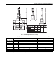
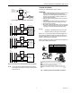
Fig. 3. V5013N replacement parts.
INSTALLATION
When Installing this Product…
1. Read these instructions carefully. Failure to follow them
could damage the product or cause a hazardous
condition.
2. Check the ratings given in the instructions and on the
product to make sure the product is suitable for your
application.
3. Installer must be a trained, experienced service
technician.
4. After installation is complete, check out product
operation as provided in these instructions.
IMPORTANT
1. Do not lift the valve by holding the stem.
2. Do not mount the valve with the stem pointed lower
than horizontal.
3. Mount the valve with the flow arrow pointed in the
direction of flow through the valve.
4. Mount the valve between aligned pipes. Mounting
the valve on pipes that are not aligned causes
leakage at the valve to pipe connection.
5. Ensure complete engagement on pipe to valve body
threads.
6. Hold the valve body with a clamp or pipe wrench on
the hexagonal fitting nearest the pipe to prevent
damage to the valve body while mounting on the
pipe. Refer to Fig. 7.
7. Be sure to allow enough room for installation and
service. Clearance for valve installation is dependent
on the actuator size and valve pipe size.
Location
Select a location where the valve, linkage (if used), and
actuator to be used are within the appropriate ambient
pressure and temperature ratings.
Leave sufficient clearance above the valve to accommodate
actuator installation and room for servicing the valve body.
(Completely install the valve body in the pipe line before
installing the actuator and linkage.)
When selecting a location for the valve, consider actuator
mounting restrictions. Modutrol IV™ Motors require
crankshafts to be mounted horizontally.
Mounting
The preferred mounting position of the valve is with the stem
vertical. Do not mount the valve with the stem more than
90 degrees from the vertical (pointing lower than horizontal).
Scale and foreign material can collect and can score the stem
and cause packing leakage. Protect the stem from damage
due to bending or scratching.
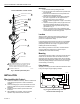
Piping Hookups
All piping must comply with local codes and ordinances. Refer
to Fig. 4 through 6 for typical piping hookups.
Fig. 4. Typical V5013N mixing valve with
constant volume through coil.
LOWER SEAT
STEM BUTTON ASSEMBLY
PACKING NUT
PACKING CARTRIDGE
VALVE BODY
PLUG ASSEMBLY
SEAT RING
O RING
1
WASHER
1
SPRING
1 2
1
2
PART INCLUDED IN REPACK KIT. 0901787A REPACK KIT
(FOR VALVES WITH 3/8 INCH STEM) SHOWN. 0901786A
REPACK KIT (FOR VALVES WITH 1/4 INCH STEM)
CONTAINS THREE PACKING WAFERS INSTEAD OF FOUR.
INCLUDED IN REBUILD KIT.
M12871
A
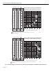
V5013N THREE-WAY GLOBE VALVES
PACKING WAFERS
1
2
2
2
2
2
2
O RING
2
2
A
AB
B
COIL
R
ETURN
SUPPLY
PUMP
PULL
PUMP
AB
A
B
BYPASS
BOILER
V5013N
M12903