
Install Instructions


® U.S. Registered Trademark
Copyright © 1999 Honeywell Inc. • All Rights Reserved
INSTALLATION INSTRUCTIONS
66-1099
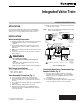
Integrated Valve Train
APPLICATION
These Integrated Gas Valve Train component installation
instructions are for small valves (3/4 in. to 2 in.) and large
valves (2 in. to 3 in.) are identical except where noted.
INSTALLATION
When Installing this product...
1. Read these instructions carefully. Failure to follow them
could damage the product or cause a hazardous
condition.
2. Check ratings given in these instructions and on the
product to make sure the product is suitable for your
application.
3. Make sure the installer is a trained, experienced service
technician.
4. Use these instructions to check out product operation
after installation.
WARNING
Fire or Explosion Hazard.
Can cause property damage, serious injury or
death.
Perform the safety shutdown test any time work is
done on a gas system.
Make sure gas is turned off before starting installation.
Bolt Torque Specifications
Torque specifications for the two bolt sizes are:
• 3/8 in. 16 bolts: 13 lb-ft.
• 1/2 in.-13 bolts: 25 lb-ft.
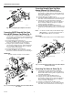
Valve Assembly Precautions (Fig. 1)
1. Use new, properly reamed, pipe, free from chips.
2. Do not thread pipe too far into pipe adapter. Valve
distortion or malfunction can result from excess pipe in
the valve.
3. Do not attach valve actuator until valve body installation
is complete.
4. Make sure O-ring sealing surfaces are clean.
5. Apply moderate amount of good quality pipe dope,
resistant to the action of liquid propane (LP) gas only
on the pipe threads.
6. Make sure the gas flow is in the direction of the arrow
on the gas valve casting.
NOTE: Gas flow in the V4297S Normally Open Vent Valve
can be in either direction.
Fig. 1. Preparing pipes.
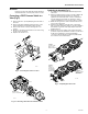
Connecting Upstream or Downstream Pipe
Adapter to Valve (Fig. 2)
1. Using the grease packet provided (or equivalent,
general purpose, lithium grease), grease the O-ring.
Make sure the grease is applied evenly around the
entire O-ring.
2. Insert the O-ring into the O-ring groove.
3. Assemble the pipe adapter to the valve using the three
bolts, nuts and lock washers as shown in Fig. 2.
INCORRECT:
CORRECT:
TWO CLEAN
THREADS
WITH
MODERATE
AMOUNT
OF DOPE
EXCESS DOPE CAN BLOCK
DISK FROM
VALVE
SEAT
LOOSE
CHIPS
CORRECT:
NORMAL
FULL
THREAD
REAM PIPE AND BLOW
OUT CHIPS (TO AVOID
LODGING ON SEAT)
TOO LONG,
DISTORTS
VALVE SEAT
TOO LONG,
DISTORTS
VALVE SEAT
M16410
1
1
USE PIPE DOPE RESISTANT TO ACTION OF LP GAS.
INCORRECT:
PIPE
ADAPTER
PIPE
ADAPTER