
Submittal Sheet


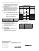
Table Of Contents

V9055A,D MODULATING FLUID POWER GAS VALVE ACTUATOR
60-2311—08 6
Fig. 4. Wiring for V9055 Modulating Gas Valve Actuator.
Fig. 5. Hookup of V9055 for firing rate
control with a 4-20 mA input.
203422C—V9055 Adapter (For 4-20 mA Input)
Installation
The 203422C Adapter Board allows the V9055 Modulating
Fluid Power Gas Valve Actuator to be controlled with a
4-20 dc mA input. The adapter mounts in the wiring
compartment and provides screw terminals for field wiring.
1. Remove the screws from terminals R,B and W on the
V9055 Actuator.
2. Position the adapter board to the R, B and W terminals
and install and tighten three screws (four screws
provided in bag assembly) to the R, B, and W terminals.
3. Connect field wiring from 4-20 mA controller to the + and
- terminals on the 203422C adapter board. Be sure to
observe polarity.
CAUTION
Equipment Damage Hazard.
Incorrect wiring can damage the controller or
adapter board.
Be sure to observe polarity from the controller to the
203422C Adapter Board.
4. Reconnect power.
5. With manual shutoff gas valve Closed, apply power to
the V9055 and check its operations with the 4-20 mA
temperature controller by manually incrementing and
decrementing the output; 4 mA input will drive the V9055
to low-fire position; 20 mA drives to high-fire. Assure
V9055 completes a full stroke.
6. Turn manual shutoff gas valve to the open position and
test the remainder of the system for proper operation.
7. If the V9055 is being used for firing rate control, connect
system according to the drawing in Fig. 5.
8. Sequence the burner through a normal startup.
CAUTION
Equipment Damage Hazard.
Improper wiring can cause equipment damage or
danger to personnel.
Label all wires prior to disconnection when servicing
valves. Wiring errors can cause improper and
dangerous operation. Verify proper operation after
servicing.
ADJUSTMENTS
IMPORTANT:
When using the V9055D with the V5055/V5097C or E
(two seals) Valves, match low-fire minimum
adjustment to the burner and the application. Too low
of an adjustment could result in loss of burner flame.
Also plan to check this low-fire adjustment at periodic
maintenance intervals.
Adjust Low-Fire Setting
The low-fire setting is adjustable from approximately 0.14 to
0.65 inch valve stem travel (with respect to V5055B/V5097B
Gas Valve). The low-fire adjustment is factory-set at the
maximum position (approximately 50 percent of full gas flow
capacity). Refer to form 70-8311 for valve flow (capacity)
curves. Check to be sure the low-fire setting is at maximum
(fully clockwise) before starting the adjustment procedure. To
adjust:
1. Remove the lead to the V9055 terminal R. Jumper termi-
nal R to W. This will prevent the actuator from going to
the high-fire position.
2. Using a Phillips screwdriver, turn the low-fire adjusting
screw to the desired low-fire position. Do not push
inward on screw.
3. Shut down the burner, and then restart. Repeat several
times to be sure the low-fire setting is suitable for correct
burner lightoff.
4. Turn off power supply. Remove R-W jumper, and
reconnect the lead to terminal R on the V9055.
Adust the Auxiliary Switch (if used)
The auxiliary switch is adjustable throughout the stroke of the
actuator. With the switch installed in the actuator, turn the
adjusting screw (Fig. 3) clockwise to cause the switch to
operate earlier in the stroke and counterclockwise to
operate later in the stroke.
2
1
2
1
WRB
1
2
WRB
L1 HOT
L2
COM
NC
NO
AUX
SWITCH
POWER SUPPLY. PROVIDE DISCONNECT MEANS
AND OVERLOAD PROTECTION AS REQUIRED.
PROPORTIONING CONTROLLER
(140 OHM POTENTIOMETER)
CIRCUIT CLOSED WITH ACTUATOR DE-ENERGIZED.
V9055 GAS VALVE ACTUATOR
M7323
12
10
11
14
[B]
[R]
[W]
+
–
+
–
4 – 20 m A
CONTROLLER
TERMINALS OF 203422C ADAPTER.
[ ]
TERMINALS TO V9055.
TERMINALS OF R4140 OR BC7000.
TERMINALS OF RM7800.
M2494A
12
13
14
15