
Owner's Manual

H_301C_DS01015_V3
10/09
© 2009 Honeywell Analytics
HWA6075
Please Note:
While every effort has been made to ensure
accuracy in this publication, no responsibility
can be accepted for errors or omissions.
Data may change, as well as legislation, and you
are strongly advised to obtain copies of the most
recently issued regulations, standards, and guidelines.
This publication is not intended to form the
basis of a contract.
© 2007 Honeywell Analytics
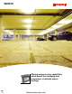
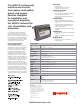
The VA301C continuously
monitors and controls
toxic gases, combustible
gases, and oxygen
hazards. Designed
for installation and
operational simplicity,
the VA301C reduces the
cost of installation and
ownership.
User Friendly
Zero maintenance•
Automatic quick self-test and warm-up•
Continuous alphanumeric display •
Inexpensive and Reliable
Low installation costs•
Allows for up to 126 zoning groups which can save •
energy and extend fan and relay life
Manages up to 768 events with programmable •
latching alarms
Flexible Operation
Modbus compatible; with BACnet/IP available•
Interchangeable transmitters able to detect different •
gases
Expands to handle up to 96 transmitters or relay •
modules and up to 50 301W wireless sensors
Programmable time delays•
Integrated time clock enables scheduling of system •
operations
Safety Measures
Full array of visual indicators and integrated 65dBA •
alarm levels
Fully programmable relays (can be set as fail-safe •
or not)
Benecial Options
Available in a heavy duty industrial housing•
Datalogging option•
General Specications
Use
Modbus controller for centralized gas detection monitoring with real-time gas reading, selective alarm activation and low
cost of installation.
Size
28 x 20.3 x 7 cm (11.02 x 7.99 x 2.76 in.)
Weight
1.1 kg (2.4 lb.)
Power Requirement
17-27 Vac, 24-38 Vdc, 500 mA
Network Capacity
Three Modbus channels for up to 96 transmitters, one wireless channel for up to 50 301W wireless transmitters and an
optional BACnet/IP output
Communication Line
Lengths
Up to 609 m (2000 ft.) per channel
T-Tap: 20 m (65 ft.), maximum per T-Tap
40 m (130 ft.), maximum for all T-Tap combined
Relay Output Rating
5 A, 30 Vdc or 250 Vac (resistive load)
Alarm Levels
3 fully programmable alarm levels
Time Delays
0, 30 sec., 45 sec., 1-99 minutes before and after alarm
Outputs
4 DPDT relays (alarms and/or fault); 65dBA buzzer
Display
Large 122 x 32 dot matrix display
Operating Humidity
Range
0-95% RH, non-condensing
Operating Temperature
Range
-20 to 50°C (-4 to 122°F)
Ratings and Certications
Certied to
CAN/CSA C22.2 No 61010-1
116662
Conforms to
ANSI/UL 61010-1
IEC 61010-1 Including Amendments A1:1992 +
A2:1995 and National Deviations (Canada, US)
Using an addressable RS-485 Modbus
communication protocol, the 301C uses
daisy chain wiring requiring only 2 pairs of
wires to connect up to 96 transmitters on the
3 input channels. This simplies installation,
in turn lowering costs. The 301C’s zoning
and averaging abilities signicantly reduce
operational and maintenance costs.
Zoning/Averaging Capabilities
Reduce Operational Costs
The 301C controller offers unique zoning
capabilities which permit the averaging and
comparison of multiple sensor readings.
Zoning can reduce operational costs by
ensuring that localized brief uctuations
registered at a single transmitter do not
activate relays. For example, a car idling in
a parking structure may locally increase a
reading at a nearby transmitter. Rather than
activating a fan as a result of the temporary
localized uctuation, zoning can be used
to limit relay activation until the average
reading for a zone exceeds a set-point.
This can reduce run time of fans, yielding
savings in both energy usage and wear and
tear. The 301C has the capacity to manage
input from three Modbus channels for up
to 96 transmitters and up to 50 wireless
transmitters which can be associated with
up to 126 zones. Transmitters can belong
to an unlimited number of zones, providing
maximum operational and control exibility.
firealarmresources.com