
Install Instructions

VB6 series 6-Way Control Ball Valves and Actuators - Installation Instructions
31-00380M-01 4
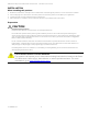
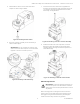
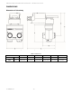
Figure 3. Actuator mounting
NOTE: Further, in order to guarantee IP54, only
original Honeywell grommets may be used.
Preparing Actuator for mounting
1. Use a suitable plier to hold the clip of the Universal
shaft adapter.
2. Pull out the Clip as shown in below figure to remove
Universal shaft adapter. Now, the actuator is ready to
assemble on 6-way control ball valve.
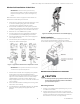
Assembling the actuator on Valve body
1. Make sure that the Gear box is in zero position as
shown in below figure. Use the appropriate wrench to
adjust (if necessary).
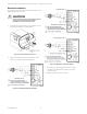
Figure 4. Zero position of Gear box on Valve body
2. Slide the actuator into Actuator pedestal as shown in
below figure. Do not use additional tools or pressure
as the Actuator pedestal is designed to press fit with
the MN7510A2001 actuator.
Figure 5. Assembly of Actuator pedestal
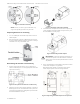
3. Insert the Stem adapter into the Actuator output hub
(Stem adapter and Output hub are keyed so they can
be assembled in one way only).
Figure 6. Assembly of Stem adapter
IMPORTANT: To prevent equipment damage, you
must remove power or set the function selection
switch to the “Service/Off” position before manual
adjustment.
4. Press and hold the Declutch button to permit rotation
of the Stem adapter to any position.
Rotate the Stem adapter, so that the notch on the
Stem adapter points as shown in figure below.
Figure 7. Adjusting the Stem adapter to zero position