
Install Instructions


VB6 series 6-Way Control Ball Valves and Actuators - Installation Instructions
3 31-00380M-01
Mechanical Installation of the Valve
IMPORTANT: Hold valve with pipe wrench by
hexagonal fitting ONLY. Do NOT handle the Valve
body with the pipe wrench; product damage may
result.
Refer Dimension section on page 9 for more details on
dimensions of Valve body and actuator.
1. Clean the lines upstream of particles larger than 1/16
in. diameter (welding slag, pipe scale and other
contaminants) to properly flush the system.
2. Proceed with installation once the system specifics
(expansion/contraction of the system and its medium
as well as operating pressures) are within tolerances.
3. Eliminate air or air-bubbles from system.
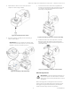
4. Use the markings on the valve bodies to familiarize
yourself with the A, B, and AB piping connections.
5. Connect the AB-ports of the valve to the supply and
return pipes of the coil.
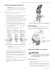
6. Connect the A-ports and B-ports as per the flow
sequences. Refer to below figure.
Figure 1. Typical flow directions for Sequence 1 and 2.
IMPORTANT: Strictly follow flow direction and port
connections as per flow sequences.
7. Clear threads on both valve and piping of any debris.
Honeywell recommends Permabond A1044 or
equivalent thread or pipe sealant. When using Teflon
tape, it is recommended to use 4-6 rounds of tape
applied tightly in clockwise rotation. When using
hemp as pipe sealant, ensure no strands are left in the
valve or piping.
8. Valves must be installed avoiding unnecessary pull or
twist in the valve housing.
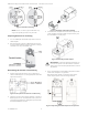
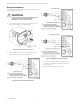
9. Use the Bracket as shown below figure if non-flexible
pipes are used in piping to keep pipes firm and
parallel.
Figure 2. Assembly of Bracket for non-flexible piping
Valve Insulation
To avoid water condensation dripping from the 6-way
valve, insulate around the pipe connections and the
structural box, but do not cover the gear box in insulation.
Mechanical Installation for Actuator
CAUTION
To avoid personal injury (electrical shock) and to
prevent equipment damage, before installation,
you must remove power.
Mounting Position
1. Choose a mounting position permitting easy access
to cables and controls.
2. Make sure that the actuator stem is in horizontal to
upright vertical position, but never in below horizontal
position. Condensate from Valve body may flow into
the Gear box or actuator, causing damage.