
Install Instructions


VB6 series 6-Way Control Ball Valves and Actuators - Installation Instructions
5 31-00380M-01
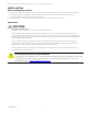
5. Slide the Brass sleeve over the end of the Stem
adapter as shown in figure below.
Figure 8. Assembly of Brass sleeve
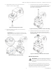
6. Place the actuator assembly on the Valve body as
shown in below figure.
IMPORTANT! The only possible way that the valve
stem and actuator Stem adapter can be assembled
together is with both in the Zero position.
Figure 9. Assembly on the Valve body.
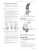
7. Insert the Screw (M4) and Washer (supplied with
package) into the linkage shaft and tighten the screw
(1.8 -2.5 Nm) to firmly assemble the actuator with
Valve body. See figure below.
Figure 10. Mounting of Screw in actuator assembly
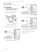
8. Hold the handle in the vertical position (as shown
below) and insert the handle on the linkage Stem
adapter knob by pressing it downwards (press fit) to
assemble it firmly.
Figure 11. Mounting of Handle on the actuator
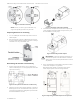
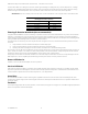
Manual Adjustment
IMPORTANT: To prevent equipment damage, you
must remove power or set the function selection
switch to the “Service/Off” position before manual
adjustment.
After removing power or setting the function selection
switch to the “Service/Off” position, the Gear box can be
disengaged using the Declutch button, permitting the
handle to be manually rotated to any position.