
Install Instructions


VB6 series 6-Way Control Ball Valves and Actuators - Installation Instructions
7 31-00380M-01
Actuator Run modes
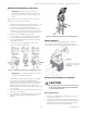
The function selection switch (see Figure 16) can be used to place the actuator into any one of two different modes:
• Modulating run mode
• Floating/2-position run mode
• Service/Off mode.
Figure 16. Function Selection Switch
Modulating Run Mode
The Modulating Run mode can be used in four different types of control settings:
• 2…10 Vdc
• 0…10 Vdc
• 10…0 Vdc
• 10…2 Vdc
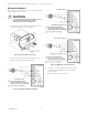
If the function selection switch has been set to one of the four modulating control settings - and if the actuator is wired
correspondingly (see Figure 13) - then as soon as operating power is applied, the shaft adapter will run first completely
counterclockwise and then completely clockwise, after which it will run according to the control signals applied.
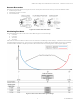
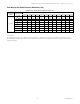
Figure 17. Flow curve with control signal settings