
Install Instructions


VB6 series 6-Way Control Ball Valves and Actuators - Installation Instructions
31-00380M-01 8
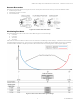
Use the above flow curve with given actuator control signal settings to configure 6-way valve for Sequence 1 (cooling),
Sequence (2), and Off-position. Note that in Figure 13 it is shown how to override the actuator with a switch on wiring
terminal 4 to go to the 50% position. This may also be used to rotate the valve to the zero (closed) position.
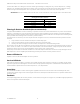
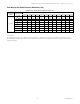
IMPORTANT: The zero (closed) position of the valve can be achieved with control signal shown in the below table.
Valve closed command
(45-degree actuator rotation)
Actuator Control Signal Setting
Controller Output
0-10 Vdc
5 Vdc
2-10 Vdc
6 Vdc
10-0 Vdc
5 Vdc
10-2 Vdc
6 Vdc
Floating/2-Position Run Mode (Not recommended)
Using the MN7510A2001 actuator in floating / 2-position mode is not recommended with 6-way valves. Because both
Sequence 1 and Sequence 2 are closed at the actuator mid-stroke, 45 degree actuator rotation, it must be possible to
command the actuator to position itself in the mid-stroke position, which is difficult to do with precision in floating mode,
and impossible when floating mode is used for 2-position control.
If it is desired to use the 6-way valve for simple seasonal changeover service, it is best if three distinct positions can be
achieved:
1. Fully clockwise actuator rotation for Sequence 2 to be fully open.
2. Fully counterclockwise actuator rotation for Sequence 1 to be fully open.
3. Exactly mid-stroke, 45-degree actuator rotation, for Sequence 1 and 2 both being closed.
This scheme can only be achieved with the actuator selector switch set to one of the four modulating modes, using 0-10
Vdc, 2-10 Vdc, 10-0 Vdc, or 10-2 Vdc to achieve full clockwise, full counterclockwise, and precisely mid-stroke actuator
positions. If desired, the actuator analog feedback can be used to verify actual position.
If only step 1 and 2 above are desired, and there is no need for step 3 to rotate the actuator to exactly 45 degrees to turn
both Sequence 1 and 2 completely off, the floating mode may be used for 3-wire 2-position control.
Power-Off Behavior
If power is removed, the shaft adapter remains in position.
Service/Off Mode
If the function selection switch is set to the “Service/Off” position, then all rotary movement is cancelled, and all control
signals are ignored, thus allowing the actuator to be manually operated safely. Press and hold the Declutch button and
use the handle to operate the actuator from Sequence 1, 2, or, Off positions.
Overriding
An override is a condition in which a 24 V signal is applied to terminal 4 of an actuator in the modulating mode, thus
causing the actuator to ignore the control signal at terminal 3, whereupon it will instead move to a position of 50% of its
maximum stroke.
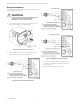
Feedback
If correspondingly wired, the actuator provides, via terminal 5 (see Figure 13 to Figure 15), a feedback signal proportional
to the actual position of the shaft adapter.