
Product Overview

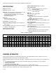


Table Of Contents

VBN2, VBN3 CONTROL BALL VALVES WITH THREADED CONNECTIONS
7 62-2648
Required Torque
Both Honeywell non-spring return and spring return low torque
direct coupled actuators can be utilized with the VBN2 and
VBN3 valves. VB valves use a patented seat design that
reduces the torque needed from the actuator. A 35 lb-in. DCA
provides sufficient torque to close the valve at rated close-off.
(See Table 6.) These ratings exceed most HVAC application
requirements.
Table 7. Close-off, Differential Pressure Ratings.
INSTALLATION
When Installing this Product...
1. Read these instructions carefully. Failure to follow them
could damage the product or cause a hazardous condi-
tion.
2. Check ratings given in instructions and on the product to
ensure the product is suitable for your application.
3. Installer must be a trained, experienced service techni-
cian.
4. After installation is complete, check out product opera-
tion as provided in these instructions.
Preparation
CAUTION
Equipment Damage Hazard
Foreign particles like dirt and metal chips can damage
the ball seals.
For trouble-free operation of the product, good
installation practice must include initial system flushing,
and chemical water treatment. Clean the lines
upstream of particles larger than 1/16 inch diameter
(welding slag, pipe scale, sand and other suspended
particulate). Use of a 50 micron (or finer) system side
stream filter is suggested. Remove all filters before
flushing.
Do not use boiler additives, solder flux and wetted
materials which are petroleum based or contain mineral
oil, hydrocarbons, or ethylene glycol acetate.
Compounds which can be used, with minimum 50%
water dilution, are diethylene glycol, ethylene glycol,
and propylene glycol (antifreeze solutions).
If installing these valves in an addition to, or retrofitting
an existing building, do not assume that the fluid in the
existing piping meets these criteria.
1. Clean the lines upstream of particles larger than 1/16 in.
diameter (welding slag, pipe scale and other contami-
nants).
2. Proceed with installation once the system specifics
(expansion/contraction of the system and its medium as
well as operating pressures) are within tolerances.
3. Eliminate air from system.
4. Two-way valves are marked to show flow direction.
IMPORTANT
Flow arrows must point in the direction of the flow for
proper operation.
NOTE: For three-way valve mounting, see Fig. 3 through 4.
Fig. 3. Three-way ball valve flow orientation (not to scale).
Fig. 4. Three-way mixing valve operation with coil bypass.
Valve Type Valve Size
Close-off Pressure
Rating (psi)
2 way
1/2”, 3/4” 130
1", 1-1/4”, 1-1/2”, 2",
2-1/2”, 3" 100
3 way
1/2”, 3/4”, 1" 50
1-1/4”, 1-1/2”, 2",
2-1/2” 40
M13737
SUPPLY
RETURN
AB PORT A PORT
B PORT
COIL
SUPPLY
RETURN
AB PORT A PORT
B PORT
COIL
MIXINGDIVERTING
AB A
B
M19523
HEATING COIL
FULL
HEAT
5 GPM
5 GPM
2.5 GPM
5 GPM
AB A
B
PROPORTIONED
HEAT
2.5 GPM
SUPPLY
MAIN
RETURN
MAIN
5 GPM
5 GPM
AB
VB3
VB3
VB3
A
B
NO
HEAT
NO FLOW
THROUGH COIL