
Install Instructions
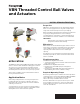

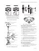
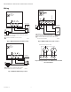

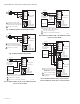
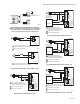

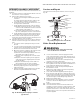

Table Of Contents

VBN THREADED CONTROL BALL VALVES AND ACTUATORS
9 62-2025EFS—06
OPERATION AND CHECKOUT
Once both the mechanical and electrical installations are
complete:
1. Cycle the actuator to verify that the direction of rota-
tion suits the control sequence.
2. If the rotation direction is incorrect:
a. For 2-position and Sylk-enabled spring return
actuators:
To change spring return direction: remove, flip
over, and replace actuator on the bracket.
b. For floating control actuators: Reverse two con-
trol signal wires (CW/CCW).
c. For modulating spring return control actuators:
(1) MS7505 actuators reposition control signal
selection switch; MS7103 actuators 2-10 Vdc
only (reversal not possible), or
(2) To change spring return direction: remove,
flip over, and replace actuator on the bracket.
d. For modulating actuators without spring return,
reposition reverse/direct acting selector switch.
3. If the control scheme requires fail-safe operation,
ensure that, upon removal of power, the fail position
coincides with the control sequence.
4. If the fail safe position is incorrect, remove and rein-
stall the actuator in the opposite orientation as fol-
lows:
a. Loosen the shaft coupling bolt using a 10 mm
wrench.
b. Loosen all other mounting bolts connecting the
actuator to the mounting bracket, and set aside.
c. Remove the actuator from the valve shaft.
d. Move the actuator coupling to the opposite side
of the actuator, as displayed in Fig. 31.
(1) Remove the retainer clip from the shaft cou-
pling and set it aside for later use.
(2) Remove shaft coupling from one side of the
actuator.
(3) Replace the shaft coupling on the opposite
side of the actuator, aligning it based on the
stroke labelling.
(4) Replace the retainer clip on the shaft cou-
pling using the groove of the coupling.
e. Reconnect the actuator to the valve mounting
bracket by replacing the screws previously
removed (step b)
f. Tighten the shaft coupling bolt using a 10 mm
wrench using maximum 120 lb-in torque.
Fig. 31. Mounting shaft coupling to actuator
opposite side.
Service and Repair
The valve stem can be replaced in-line, if necessary. See
Fig. 32.
Fig. 32. Replacing the valve stem in-line.
Valve Stem Replacement
WARNING
Scratching the inside of the valve neck may
cause a leak when re-assembled.
1. Close isolation valves on both supply and return
sides of the Honeywell control valve. (If there are no
isolation valves, turn off the circulation pump). Valve
body must be de-pressurized.
2. Relieve excess pressure from isolated portion by
opening an air vent or drain valve.
3. Remove the actuator. Ensure that the valve is closed.
The T symbol on the stem should be oriented like it is
in the right-side drawing in Fig. 33 below.
4. Remove the 2 screws securing the adapter plate.
Discard these screws.
5. Remove the stem, making sure the lower packing
gland is removed, and discard.
6. Cover new stem with supplied protective grease.
7. Insert the new stem. Be sure to align the key on the
bottom of the stem with the slot in the ball, and the T
symbol of the new stem is aligned exactly as the old
one, like the right-side drawing in Fig. 33 below.
8. Replace the adapter plate.
9. Tighten the two new, supplied, screws to 16.5 lb in
(+-10%) to attach the adapter plate to the valve
body.
10. Open the isolation valves.
11. Once mechanical and electrical installations are
complete, cycle the actuator to verify operation, and
that the direction of rotation matches the control
signal. If the actuator is a fail-safe model, make sure
that the valve is in the correct position when there is
no power applied.
M19579A
STEM
ASSEMBLY
COUNTERSUNK
SCREWS
STEM RETAINER
PLATE
“T” SYMBOL
STEM
UPPER PACKING
GLAND
O-RING
LOWER PACKING
GLAND
M34994